EV20F92A Serial Memory SPI Evaluation Kit User’s Guide
2022 Microchip Technology Inc. and its subsidiaries
DS20006685A-page 19
2.5
EVALUATION KIT SETUP PROCEDURE
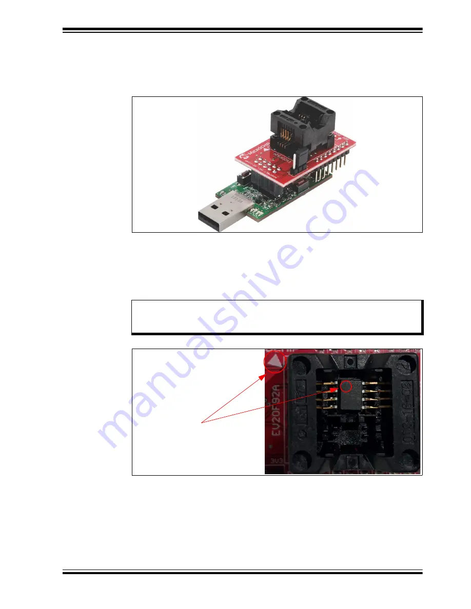
In order to start using the evaluation kit, simply plug the SPI Socket Board into the
USB Base Board using the H1 and J1 headers. See
for illustration.
FIGURE 2-13:
USB BASE BOARD AND SPI SOCKET BOARD
Once both boards are connected, verify that there is a device correctly installed in the
SOIC socket on the SPI Socket Board, making sure to note that the Pin 1 indicator on
the PCB matches the Pin 1 indicator on the SPI device. To ensure robust GUI and hard-
ware operation, it is recommended that when installing a device, the USB Base Board
be disconnected from the user’s PC.
illustrates an SPI device that is prop-
erly seated in the SOIC socket and highlights the pin 1 indicator on the PCB.
FIGURE 2-14:
SPI DEVICE IN SOIC SOCKET
Once a device is installed in the SOIC socket, the user can then plug the USB Base
Board into one of their computer’s USB ports. Once the USB Base Board enumerates
on the user’s PC, open the GUI by selecting either the desktop icon (SPI GUI) or nav-
igating to the Start Menu folder that was created when the EV20F92A SPI Evaluation
Kit GUI software was installed.
Note:
Due to the small size of the 8-lead SOIC package, it is recommended to use
tweezers in order to properly install the device into the SPI Socket Board
socket.
Pin 1 Indicators


