


dsPIC30F6010
DS70119B-page 138
Advance Information
2004 Microchip Technology Inc.
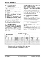
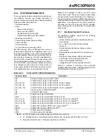
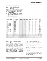
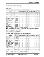
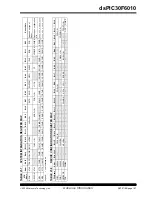
21.2.4
PHASE LOCKED LOOP (PLL)
The PLL multiplies the clock which is generated by the
primary oscillator. The PLL is selectable to have either
gains of x4, x8, and x16. Input and output frequency
ranges are summarized in Table 21-3.
TABLE 21-3:
PLL FREQUENCY RANGE
The PLL features a lock output, which is asserted when
the PLL enters a phase locked state. Should the loop
fall out of lock (e.g., due to noise), the lock signal will be
rescinded. The state of this signal is reflected in the
read only LOCK bit in the OSCCON register.
21.2.5
FAST RC OSCILLATOR (FRC)
The FRC oscillator is a fast (8 MHz nominal) internal
RC oscillator. This oscillator is intended to provide rea-
sonable device operating speeds without the use of an
external crystal, ceramic resonator, or RC network.
The dsPIC30F operates from the FRC oscillator when-
ever the Current Oscillator Selection control bits in the
OSCCON register (OSCCON<13:12>) are set to ‘
01
’.
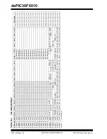
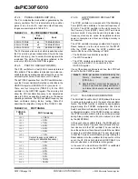
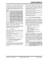
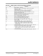
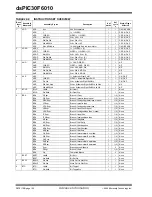
There are four tuning bits (TUN<3:0>) for the FRC
oscillator in the OSCCON register. These tuning bits
allow the FRC oscillator frequency to be adjusted as
close to 8 MHz as possible, depending on the device
operating conditions. The FRC oscillator frequency has
been calibrated during factory testing. Table 21-4
describes the adjustment range of the TUN<3:0> bits.
TABLE 21-4:
FRC TUNING
21.2.6
LOW POWER RC OSCILLATOR
(LPRC)
The LPRC oscillator is a component of the Watchdog
Timer (WDT) and oscillates at a nominal frequency of
512 kHz. The LPRC oscillator is the clock source for
the Power-up Timer (PWRT) circuit, WDT and clock
monitor circuits. It may also be used to provide a low
frequency clock source option for applications where
power consumption is critical, and timing accuracy is
not required.
The LPRC oscillator is always enabled at a Power-on
Reset, because it is the clock source for the PWRT.
After the PWRT expires, the LPRC oscillator will
remain ON if one of the following is TRUE:
• The Fail-Safe Clock Monitor is enabled
• The WDT is enabled
• The LPRC oscillator is selected as the system
clock via the COSC<1:0> control bits in the
OSCCON register
If one of the above conditions is not true, the LPRC will
shut-off after the PWRT expires.
21.2.7
FAIL-SAFE CLOCK MONITOR
The Fail-Safe Clock Monitor (FSCM) allows the device
to continue to operate even in the event of an oscillator
failure. The FSCM function is enabled by appropriately
programming the FCKSM configuration bits (Clock
Switch and Monitor Selection bits) in the F
OSC
device
configuration register. If the FSCM function is enabled,
the LPRC Internal oscillator will run at all times (except
during Sleep mode) and will not be subject to control
by the SWDTEN bit.
In the event of an oscillator failure, the FSCM will gen-
erate a Clock Failure Trap event and will switch the sys-
tem clock over to the FRC oscillator. The user will then
have the option to either attempt to restart the oscillator
or execute a controlled shutdown. The user may decide
to treat the Trap as a warm Reset by simply loading the
Reset address into the oscillator fail trap vector. In this
event, the CF (Clock Fail) status bit (OSCCON<3>) is
also set whenever a clock failure is recognized.
In the event of a clock failure, the WDT is unaffected
and continues to run on the LPRC clock.
Fin
PLL
Multiplier
Fout
4 MHz-10 MHz
x4
16 MHz-40 MHz
4 MHz-10 MHz
x8
32 MHz-80 MHz
4 MHz-7.5 MHz
x16
64 MHz-120 MHz
TUN<3:0>
Bits
FRC Frequency
0111
+ 10.5%
0110
+ 9.0%
0101
+ 7.5%
0100
+ 6.0%
0011
+ 4.5%
0010
+ 3.0%
0001
+ 1.5%
0000
Center Frequency (oscillator is
running at calibrated frequency)
1111
- 1.5%
1110
- 3.0%
1101
- 4.5%
1100
- 6.0%
1011
- 7.5%
1010
- 9.0%
1001
- 10.5%
1000
- 12.0%
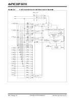
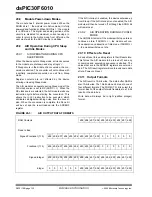
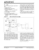
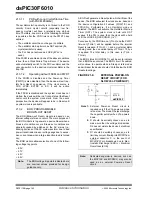
Note 1:
OSC2 pin function is determined by the
Primary Oscillator mode selection
(FPR<3:0>).
2:
Note that OSC1 pin cannot be used as an
I/O pin, even if the secondary oscillator or
an internal clock source is selected at all
times.
Содержание dsPIC30F6010
Страница 12: ...dsPIC30F6010 DS70119B page 10 Advance Information 2004 Microchip Technology Inc NOTES...
Страница 32: ...dsPIC30F6010 DS70119B page 30 Advance Information 2004 Microchip Technology Inc NOTES...
Страница 38: ...dsPIC30F6010 DS70119B page 36 Advance Information 2004 Microchip Technology Inc NOTES...
Страница 50: ...dsPIC30F6010 DS70119B page 48 Advance Information 2004 Microchip Technology Inc NOTES...
Страница 68: ...dsPIC30F6010 DS70119B page 66 Advance Information 2004 Microchip Technology Inc NOTES...
Страница 72: ...dsPIC30F6010 DS70119B page 70 Advance Information 2004 Microchip Technology Inc NOTES...
Страница 76: ...dsPIC30F6010 DS70119B page 74 Advance Information 2004 Microchip Technology Inc NOTES...
Страница 86: ...dsPIC30F6010 DS70119B page 84 Advance Information 2004 Microchip Technology Inc NOTES...
Страница 108: ...dsPIC30F6010 DS70119B page 106 Advance Information 2004 Microchip Technology Inc NOTES...
Страница 116: ...dsPIC30F6010 DS70119B page 114 Advance Information 2004 Microchip Technology Inc NOTES...
Страница 128: ...dsPIC30F6010 DS70119B page 126 Advance Information 2004 Microchip Technology Inc NOTES...
Страница 150: ...dsPIC30F6010 DS70119B page 148 Advance Information 2004 Microchip Technology Inc NOTES...
Страница 164: ...dsPIC30F6010 DS70119B page 162 Advance Information 2004 Microchip Technology Inc NOTES...
Страница 208: ...dsPIC30F6010 DS70119B page 206 Advance Information 2004 Microchip Technology Inc NOTES...
Страница 220: ...dsPIC30F6010 DS70119B page 220 Advance Information 2004 Microchip Technology Inc NOTES...
Страница 221: ...2004 Microchip Technology Inc Advance Information DS70119B page 221 dsPIC30F6010 NOTES...


