background image

DM160232 Serial Memory Single-Wire Evaluation Kit User’s Guide

 2018 Microchip Technology Inc.

DS20005939A-page 36

4.2

INSTALLING THE GRAPHICAL USER INTERFACE (GUI)

Once the FLIP Software Utility has been successfully installed on the user’s PC, the 
next step is to download and install the latest version of the DM160232 SWI Graphical 
User Interface (GUI) software.

The following steps are necessary to successfully install the GUI software:

1.

Go to 

http://www.microchip.com/DM160232 

to download the GUI software.

2.

Navigate to “Documentation and Software” and select the “DM160232 SWI GUI 
software”.

3.

Download and open the setup file.


DM160232_x.x.x_setup.exe

 (

x.x.x

 indicate the GUI version)

4.

Install the GUI using the procedure outlined in 

Section 2.3 “Installing the 

Graphical User Interface (GUI)”

.

4.3

USB BASE BOARD DFU MODE

Once the latest version of the GUI has been installed on the user’s PC, the next step 
is to plug in the USB Base Board into a USB port without the SWI Socket Board 
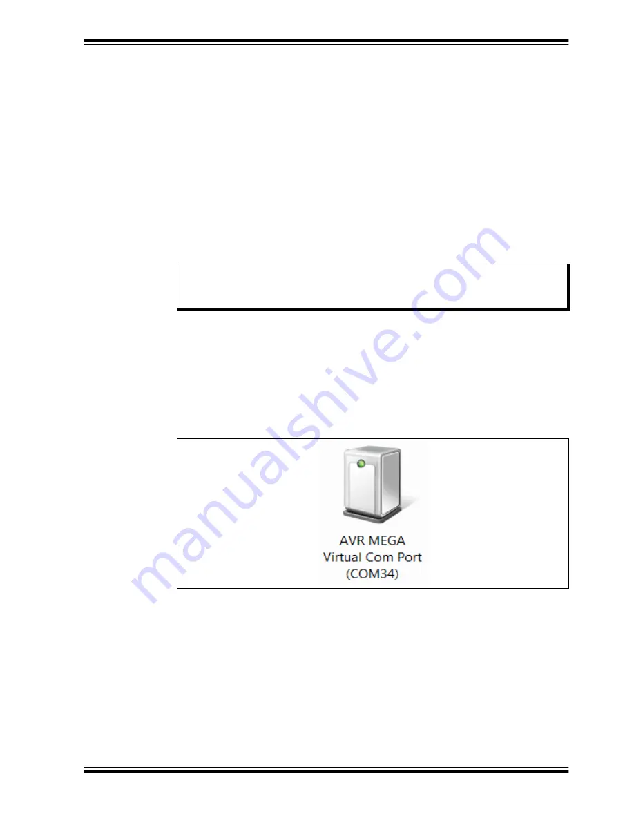
connected. The PC will recognize the USB Base Board as “AVR MEGA Virtual Com 
Port” in the PC’s Devices and Printers


window from the Control Panel if there is 

firmware already loaded in the USB Base Board (

Figure 4-10

). Note that the COM port 

numeration may change based on the user’s PC.

FIGURE 4-10:

AVR MEGA VIRTUAL COM PORT

Note:

If an earlier version of the SWI GUI was previously installed, it is recom-
mended to uninstall the previous version before installing the new version. 
This will ensure robust GUI operation.

Содержание DM160232

Страница 1: ... 2018 Microchip Technology Inc DS20005939A DM160232 Serial Memory Single Wire Evaluation Kit User s Guide ...

Страница 2: ...eceived ISO TS 16949 2009 certification for its worldwide headquarters design and wafer fabrication facilities in Chandler and Tempe Arizona Gresham Oregon and design centers in California and India The Company s quality system processes and procedures are for its PIC MCUs and dsPIC DSCs KEELOQ code hopping devices Serial EEPROMs microperipherals nonvolatile memory and analog products In addition ...

Страница 3: ...GUI 12 2 4 Evaluation Kit Setup Procedure 15 Chapter 3 Graphical User Interface GUI 3 1 Introduction 17 3 2 Main Title Bar 18 3 3 Query Device 18 3 4 System Status 18 3 4 1 Kit Part Number 18 3 4 2 Firmware Revision 19 3 4 3 Socket Board Temp 19 3 4 4 Device in Socket 19 3 4 5 Kit Protocol 19 3 4 6 Socket Board SN 19 3 5 Device Conditions 19 3 5 1 Supply Voltage Slider 19 3 5 2 Frequency Kbps Slid...

Страница 4: ...Array Buttons 27 3 13 1 Read 27 3 13 2 Write 28 3 13 3 Go To Address 29 3 13 4 Other Actions 30 3 13 5 Support 30 Chapter 4 USB Base Board Firmware Upgrade 4 1 Introduction 31 4 2 Installing the Graphical User Interface GUI 36 4 3 USB Base Board DFU Mode 36 4 4 FLIP Software Utility 38 Chapter 5 Troubleshooting Guide Appendix A Schematics A 1 Introduction 44 A 2 SWI Socket Board 02 10681 45 A 3 US...

Страница 5: ...allation and Operation Chapter 3 Graphical User Interface GUI Chapter 4 USB Base Board Firmware Upgrade Chapter 5 Troubleshooting Guide Appendix A Schematics Appendix B Bill of Materials BOM NOTICE TO CUSTOMERS All documentation becomes dated and this manual is no exception Microchip tools and documentation are constantly evolving to meet customer needs so some actual dialogs and or tool descripti...

Страница 6: ... File Save Bold characters A dialog button Click OK A tab Click the Power tab N Rnnnn A number in verilog format where N is the total number of digits R is the radix and n is a digit 4 b0010 2 hF1 Text in angle brackets A key on the keyboard Press Enter F1 Courier New font Plain Courier New Sample source code define START Filenames autoexec bat File paths c mcc18 h Keywords _asm _endasm static Com...

Страница 7: ...t browser the website contains the following information Product Support Data sheets and errata application notes and sample programs design resources user s guides and hardware support documents latest software releases and archived software General Technical Support Frequently Asked Questions FAQs technical support requests online discussion groups Microchip consultant program member listing Bus...

Страница 8: ...ICD 3 in circuit debugger and MPLAB PM3 device programmers Also included are nonproduction development programmers such as PICSTART Plus and PICkit 2 and 3 CUSTOMER SUPPORT Users of Microchip products can receive assistance through several channels Distributor or Representative Local Sales Office Field Application Engineer FAE Technical Support Customers should contact their distributor representa...

Страница 9: ...t devices to share a common single wire bus The device is optimized for use in many industrial and commercial applications where low power and low voltage operation are essential Some applications examples include analog sensor calibration data storage ink and toner printer cartridge identification and management of after market consumables The family is available in space saving package options a...

Страница 10: ...ices for the DM160232 Serial Memory Single Wire Evaluation Kit 1 6 OPERATIONAL REQUIREMENTS For the Serial Memory Single Wire Evaluation Kit to function properly the following hardware and software requirements must be met PC compatible system An available USB port on PC At least 1 8 MB of free disk space Windows 7 or higher operating systems 1 Note 1 Testing has been performed on a 64 bit Windows...

Страница 11: ...ASE BOARD DRIVER The following steps are needed to successfully install the USB Base Board driver 1 Go to http www microchip com DM160232 to download the USB Base Board driver 2 Navigate to Documentation and Software and select the USB Base Board Driver 3 Download and open the setup file indicated below driver atmel bundle 7 0 888 exe 4 If the Open File Security Warning pops up press the Run butto...

Страница 12: ...x x x_setup exe where x x x indicates the GUI version 4 If the Open File Security Warning pops up press the Run button 5 Select the Installation Destination Location from the Graphical User Interface GUI Press the Next button when ready Figure 2 3 The default Destination Location is C Program Files x86 Microchip Serial Memory Evaluation Kits Single Wire Close button Note If an earlier version of t...

Страница 13: ...IGURE 2 3 GUI INSTALLATION LOCATION 6 The next step is to select the Start Menu folder By default the setup will create a Start Menu folder named Microchip if one is not already present on the user s PC Press the Next button when ready to continue Figure 2 4 FIGURE 2 4 GUI START MENU FOLDER Next button Next button ...

Страница 14: ...ompt the user if they are ready to install the software Press the Install button when ready Figure 2 5 FIGURE 2 5 GUI READY TO INSTALL 8 Let the program setup the SWI GUI A progress or status bar is included to show the overall progress of the installation Once completed press the Finish button to complete the SWI GUI installation Figure 2 6 FIGURE 2 6 GUI INSTALLATION COMPLETE Install button Fini...

Страница 15: ...alling a supported device the USB Base Board be disconnected from the user s PC Figure 2 8 illustrates a supported device which is properly seated in the SOT23 socket Once the device is seated properly close the socket lid to finish installing the supported device FIGURE 2 8 SUPPORTED DEVICE IN SOT23 SOCKET Once a supported device is installed in the SOT23 socket the user can then plug in the USB ...

Страница 16: ...DM160232 Serial Memory Single Wire Evaluation Kit User s Guide 2018 Microchip Technology Inc DS20005939A page 16 NOTES ...

Страница 17: ...n the subsequent sections the GUI features and functions are explained in detail to help the user to interact with the installed single wire Serial EEPROM The GUI version and USB Base Board firmware version must match in order to use the GUI If the GUI and USB Base Board versions do not match and the USB Base Board has an earlier version programmed perform a USB Base Board device firmware upgrade ...

Страница 18: ...3 The Device Query feature utilizes the Single Wire Interface SWI Reset and Discovery Response feature in order to determine whether the supported device was installed properly Querying the device will populate or re populate the GUI with the content read from the installed device FIGURE 3 3 QUERY DEVICE FIGURE 3 4 DEVICE QUERY PROGRESS BAR 3 4 SYSTEM STATUS The System Status pane is populated wit...

Страница 19: ...Device Conditions pane Figure 3 6 allows the user to set the supply voltage to the SWI Socket Board and the communication speed or frequency of the Single Wire Interface SWI protocol FIGURE 3 6 DEVICE CONDITIONS PANE 3 5 1 Supply Voltage Slider The voltage slider provides the ability to change the supply voltage to the SWI Socket Board along with the installed device VPUP voltage The VPUP refers t...

Страница 20: ...ister the lock state of the Security register and the lock state of the memory zones Zone 0 Zone 3 Figure 3 7 FIGURE 3 7 DEVICE STATUS PANE 3 6 1 Serial Number Displays the serial number read from the Security register of the installed supported device The serial number is displayed in hexadecimal 3 6 2 Slave Address Displays the preprogrammed device slave address of the installed device The slave...

Страница 21: ...n to the right of that memory region The button also indicates the current lock status of that zone or the Security register and the button shading is based on the current lock status Once a button is pressed a warning message is displayed to make sure the user intends to lock that zone or the Security register FIGURE 3 8 SET DEVICE PROTECTION PANE 3 8 DEVICE SPECIFICATION The Device Specification...

Страница 22: ...ingle wire protocol 3 9 2 Export Log The EXPORT LOG button exports the Transaction Log in HTML format The exported Transaction Log can be used as a reference without having to resend protocol to the installed device 3 9 3 Legend The Transaction Log legend highlights the different data bytes in the single wire protocol that is being sent received the device address byte is shown in red the word add...

Страница 23: ...g indicates that cell or cells have been locked and now functions as Read Only Memory ROM Yellow shading indicates that the memory array cell or cells have been changed in the internal GUI buffer and have not been written to the Serial EEPROM see Section 3 11 5 PROGRAM for additional information FIGURE 3 11 MEMORY ARRAY When the user hovers the mouse cursor over the GUI memory array a pop up appea...

Страница 24: ...nformation Interchange ASCII format 3 11 3 LOAD The LOAD button gives the user the option to load a previous saved GUI memory array either HEX hex or TEXT txt file The file once loaded will be used to populate the internal GUI buffer Once the file is loaded in the GUI array buffer the user must program the installed device using the PROGRAM button see Section 3 11 5 PROGRAM for additional informat...

Страница 25: ... the data in the internal GUI buffer will not be written to the Serial EEPROM The Program feature can also be used to lock the four memory zones and or the Security register Each zone and the Security register can be locked independently of each other by placing a check mark in the corresponding box When the Program feature is used to program the Serial EEPROM memory array or Security register tha...

Страница 26: ...REGISTER The Security register consists of a factory programmed unique serial number in the lower 8 bytes address 0x00h to 0x07h an 8 byte page that is reserved for future use with data of 0xFFh address 0x08 to 0x0F and a writable portion in the upper 16 bytes address 0x10h to 0x1Fh of the Security register The red shaded cells indicate they are locked and cannot be modified by the user green shad...

Страница 27: ...ng word address using the Memory Address field that the read operation will start at in hexadecimal the Read Count or the amount of bytes to be read and the user can select what read operation is to be performed Memory Array Serial Number or Security Register Once all the input data has been filled press the READ button to start the read operation A status message is included at the bottom of the ...

Страница 28: ...ation to be performed The user inputs the data that is to be written in the Data field in hexadecimal The user then selects the starting word address using the Memory Address hex field that the write operation will start at in hexadecimal The Count or the number of bytes to be written is filled automatically based on the amount of data bytes in the Data field The user can also select whether the w...

Страница 29: ...he GUI is updated accordingly FIGURE 3 22 WRITE OPERATION 3 13 3 Go To Address The Go To Address feature allows the user to jump to a specific word address in the GUI memory array Once the Go To Address button is pressed the memory address that was input will be highlighted in a black box in the GUI memory array FIGURE 3 23 GO TO ADDRESS Note Due to the construction of the Serial EEPROM devices th...

Страница 30: ...hancements are made 3 13 5 Support The SUPPORT button provides a hyperlink to various support pages The support feature allows the user to select between three support classes Contact Support which directs the user to the Microchip support portal Order more Samples which directs the use to microchipDIRECT Find other Devices which directs the user to Microchip Serial EEPROM memory page FIGURE 3 24 ...

Страница 31: ...ww microchip com DM160232 to download the FLIP Software Utility 2 Navigate to Documentation and Software and select the FLIP Software Utility 3 Download and open the setup file JRE Flip Installer x x x xxx exe x x x xxx indicates the version 4 Once the setup file is opened if Java Runtime is already installed or a newer version is already installed the setup will automatically start and you may sk...

Страница 32: ...allation Once completed press the Close button FIGURE 4 2 JAVA RUNTIME INSTALLATION 6 When prompted select Typical setup and press the Accept button to accept the License Agreement FIGURE 4 3 JAVA RUNTIME TYPICAL SETUP Note For this example the Typical setup was used If the user selects a Custom setup it is the user s responsibility to ensure the FLIP Software Utility is installed correctly Close ...

Страница 33: ...tatus bar is included to show the overall progress of the installation Once completed press the Finish button to complete the Java Runtime installation FIGURE 4 4 JAVA RUNTIME COMPLETION 8 Once the Java Runtime is installed the FLIP Setup Wizard is automatically started Once ready click the Next button to continue FIGURE 4 5 FLIP SETUP WIZARD Finish button Next button ...

Страница 34: ...xt button to continue FIGURE 4 6 FLIP LICENSE AGREEMENT 10 The next step is to select the installation location The default installation location is set to C Program Files x86 Atmel Flip x x x x x x indicates the version It is recommended that the default installation location is used Once the installation location has been selected press the Next button FIGURE 4 7 FLIP INSTALLATION LOCATION I acc...

Страница 35: ...e default Start Menu folder is used Once ready press the Install button to continue FIGURE 4 8 FLIP START MENU FOLDER 12 Let the program setup the FLIP Software Utility A progress or status bar is included to show the overall progress of the installation Click the Next button during the installation progress if prompted Once completed press the Finish button to complete the FLIP Software Utility i...

Страница 36: ...exe x x x indicate the GUI version 4 Install the GUI using the procedure outlined in Section 2 3 Installing the Graphical User Interface GUI 4 3 USB BASE BOARD DFU MODE Once the latest version of the GUI has been installed on the user s PC the next step is to plug in the USB Base Board into a USB port without the SWI Socket Board connected The PC will recognize the USB Base Board as AVR MEGA Virtu...

Страница 37: ... hold sequence shown below to enable DFU mode on the USB Base Board Press and hold the HWB button Press and release the RESET button Release the HWB button Once the USB Base Board has DFU mode enabled allow the PC to relearn the USB Base Board as AT90USB128 DFU Figure 4 12 If the PC does not automatically recognize the USB Base Board as stated above and shown below it is recommended to unplug the ...

Страница 38: ...ng sequence using the FLIP Software Utility to upgrade the USB Base Board firmware 1 Open the FLIP Software Utility Figure 4 13 by either selecting the desktop icon if created or selecting Flip x x x x x x indicates the version from the Start Menu folder FIGURE 4 13 FLIP SOFTWARE UTILITY 2 After opening the FLIP Software Utility navigate to the Device Selection icon as shown below Select the AT90U...

Страница 39: ...DM160232 Serial Memory Single Wire Evaluation Kit User s Guide 2018 Microchip Technology Inc DS20005939A page 39 FIGURE 4 14 DEVICE SELECTION Device Selection icon AT90USB1287 ...

Страница 40: ...elow and select USB Once USB is selected an additional dialog box is displayed Press the Open button to continue FIGURE 4 15 COMMUNICATION MEDIUM SELECTION 4 Once the communication between the PC and the AT90USB1287 USB Base Board microcontroller has been established navigate to File and select Load HEX Files as shown in Figure 4 16 FIGURE 4 16 LOAD FILE Communication Medium icon USB File Load HEX...

Страница 41: ... Verified Pass is reported in the FLIP Software Utility see Figure 4 18 close the FLIP Software Utility and remove the USB Base Board from the PC The USB Base Board Firmware Upgrade procedure is complete If the Verified Pass is not shown or any other error is displayed it is recommended to unplug the USB Base Board from the PC and restart the entire firmware upgrade procedure FIGURE 4 18 FLIP SOFT...

Страница 42: ...MUST PERFORM A FIRMWARE UPDATE TO THE USB BASE BOARD SOLUTION Perform the USB Base Board Firmware Upgrade using the procedure outlined in Chapter 4 USB Base Board Firmware Upgrade ISSUE GUI STATES THERE IS NO DEVICE INSTALLED IN THE SWI SOCKET BOARD SOLUTION Close the GUI and remove the USB Base Board from the PC Verify that the SWI Socket Board and the USB Base Board are connected properly Also v...

Страница 43: ...DM160232 Serial Memory Single Wire Evaluation Kit User s Guide 2018 Microchip Technology Inc DS20005939A page 43 NOTES ...

Страница 44: ... 1 INTRODUCTION This appendix contains the following schematics for the DM160232 Serial Memory Single Wire Evaluation Kit SWI Socket Board 02 10681 USB Base Board 02 10682 Note Electronic versions of the SWI Socket Board and USB Base Board sche matics can be downloaded from http www microchip com DM160232 under Documentation and Software ...

Страница 45: ...DM160232 Serial Memory Single Wire Evaluation Kit User s Guide 2018 Microchip Technology Inc DS20005939A page 45 A 2 SWI SOCKET BOARD 02 10681 ...

Страница 46: ... 2 R 1 4 4 4 7 K 1 1 2 R103 825 2 1 2 R104 825 1 2 3 4 Y1 2 1 1 6 M H z X tal 3 1 2 R105 825 1 2 R 6 1 8 0 1 2 R7 180 1 2 L1 10uH 1 2 R 3 DN I 1 2 R 4 0 1 u F 1 VCC 2 VIN 3 GND 4 CS 5 SDO 6 SCK 7 CPAD U2 LTC2450 1 VDD 2 CS 3 SCK 4 SDI 5 LDAC 6 VREF 7 VSS 8 VOUT U3 MCP4921T E MS 1 2 C15 0 1uF 1 2 C16 0 1uF 1 2 C18 0 1uF C101 1 0uF C102 1 0uF C103 10uF 1 VIN 2 G N D 3 EN 4 BYPASS 5 OUT U1 576 1281 1...

Страница 47: ...Technology Inc AT21CS01 STUM10 T 4 N A Loose Atmel 1 Kb Serialized SWI device SOT23 Microchip Technology Inc AT21CS01 STUM10 T Note 1 The components listed in this Bill of Materials are representative of the PCB assembly The released BOM used in manufacturing uses all RoHS compliant components TABLE B 2 USB BASE BOARD 02 10682 1 Qty Reference Description Manufacturer Part Number 3 1 2 3 LED RED CL...

Страница 48: ...071KL 2 R5 R8 Resistor SMD 2K Ohm 5 1 10W 0603 Yageo Corporation RC0603JR 072KL 2 R6 R7 Resistor SMD 180 Ohm 5 1 10W 0603 Yageo Corporation RC0603JR 07180RL 1 R9 Resistor SMD 499K Ohm 1 1 10W 0603 Yageo Corporation RC0603FR 07499KL 2 R10 R11 Resistor SMD 0 0 Ohm Jumper 1 10W 0603 Yageo Corporation RC0603JR 070RL 1 R13 Resistor SMD 0 0 Ohm Jumper 1 16W 0402 Yageo Corporation RC0402JR 070RL 1 R14 Re...

Страница 49: ...nalog Devices Inc AD8531ARTZ REEL7 1 U6 IC V Level XLATR FM I2C 8 VSSOP Texas Instruments TCA9617ADGKR 4 U7 U8 U9 U10 Translator bidirectional SGL LL SC70 6 Analog Devices Inc ADG3301BKSZ REEL7 1 USB Plug connector USB 4 positions right angle PCB Molex LLC 0480370001 1 Y121 Crystal 16 0000 MHz 18 pF SMD Abracon LLC ABM3B 16 000MHZ B2 T TABLE B 2 USB BASE BOARD 02 10682 CONTINUED 1 Qty Reference De...

Страница 50: ...300 China Xian Tel 86 29 8833 7252 China Xiamen Tel 86 592 2388138 China Zhuhai Tel 86 756 3210040 ASIA PACIFIC India Bangalore Tel 91 80 3090 4444 India New Delhi Tel 91 11 4160 8631 India Pune Tel 91 20 4121 0141 Japan Osaka Tel 81 6 6152 7160 Japan Tokyo Tel 81 3 6880 3770 Korea Daegu Tel 82 53 744 4301 Korea Seoul Tel 82 2 554 7200 Malaysia Kuala Lumpur Tel 60 3 7651 7906 Malaysia Penang Tel 6...

Отзывы: