


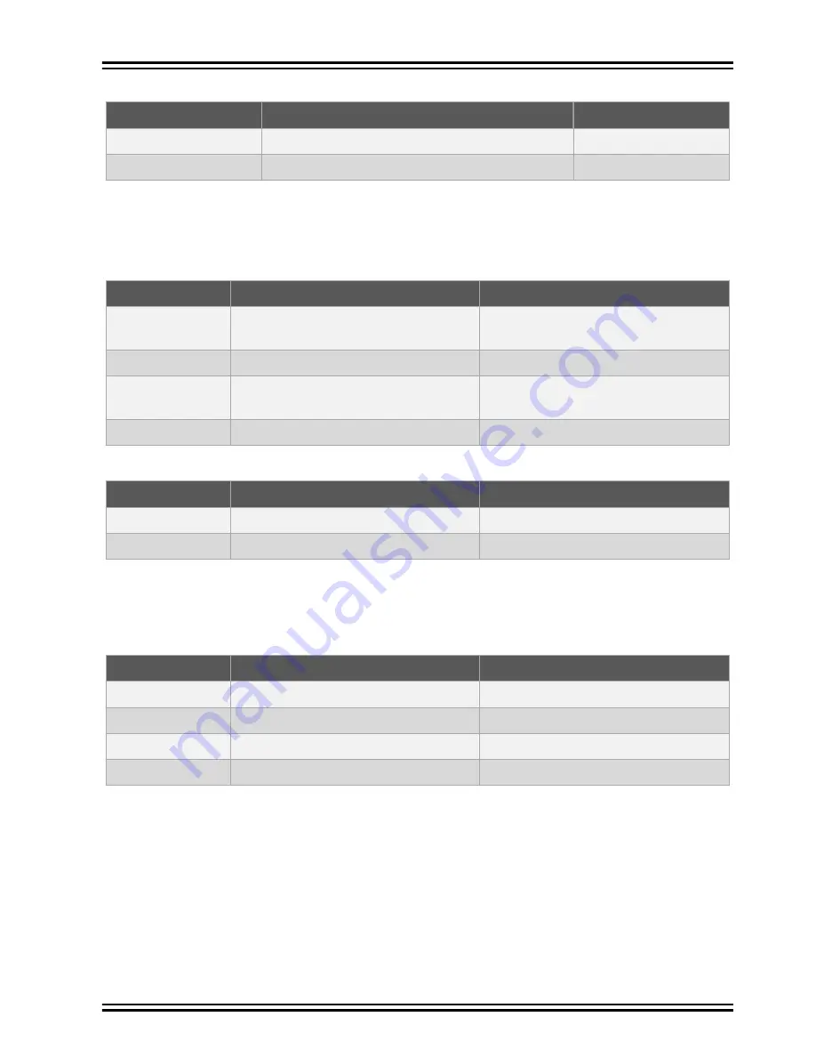
Table 4-12. Virtual COM Port Connections
SAM B11ZR pin
Function
Shared functionality
LP_GPIO_2
RX line
EXT1,EXT3
LP_GPIO_3
TX line
EXT1,EXT3
4.3.3
Data Gateway Interface
The Embedded Debugger features an Data Gateway Interface (DGI) by using either an SPI or I²C. The
DGI can be used to send a variety of data from the ATSAMB11ZR to the host PC.
Table 4-13. DGI Interface Connections When Using SPI
SAM B11ZR pin
Function
Shared functionality
LP_GPIO_12
GPIO/SPI SS (Slave select) (SAM
B11ZR is Master)
EXT1
LP_GPIO_13
SPI MISO (Master In, Slave Out)
EXT1
LP_GPIO_11
SERCOM5 PAD[2] SPI MOSI (Master
Out, Slave in)
EXT1
LP_GPIO_10
SERCOM5 PAD[3] SPI SCK (Clock Out) EXT1
Table 4-14. DGI Interface Connections When Using I²C
SAM B11ZR pin
Function
Shared functionality
LP_GPIO_8
SDA (Data line)
LP_GPIO_9
SCL (Clock line)
Four GPIO lines are connected to the Embedded Debugger. The EDBG can monitor these lines and time
stamp pin value changes. This makes it possible to accurately time stamp events in the SAM B11ZR
application code.
Table 4-15. GPIO Lines Connected to the EDBG
SAM B11ZR pin
Function
Shared functionality
LP_GPIO_16
GPIO0
LP_GPIO_17
GPIO1
EXT1, EXT3
LP_GPIO_18
GPIO2
EXT1, EXT3
LP_GPIO_19
GPIO3
EXT3
4.3.4
SAM B11ZR Xplained Pro XAM Configuration
On the SAM B11ZR Xplained Pro the MCU and the MCU peripherals (e.g. extensions) are powered by
their own regulator, as shown in the following figure. All other parts of the board, mainly the embedded
debugger and accompanying Xplained Pro Analog Module (XAM), are powered from a separate
regulator. The current to the MCU and peripherals can be measured by connecting them to the XAM
output through jumper settings.
ATSAMB11ZR
©
2017 Microchip Technology Inc.
User Guide
DS70005334A-page 18


