Output Wiring
continued
RFT9739 Rack-Mount Transmitter Instruction Manual
31
O
u
tp
ut Wi
ri
ng
Star
tu
p
T
ro
u
b
le
s
hoo
ting
Be
fo
re
Y
o
u
B
e
g
in
Getti
ng Sta
rted
M
oun
ting
P
o
w
e
r-
Suppl
y and
Sen
s
or Wi
ri
ng
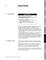
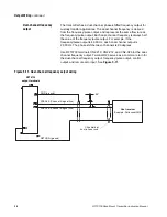
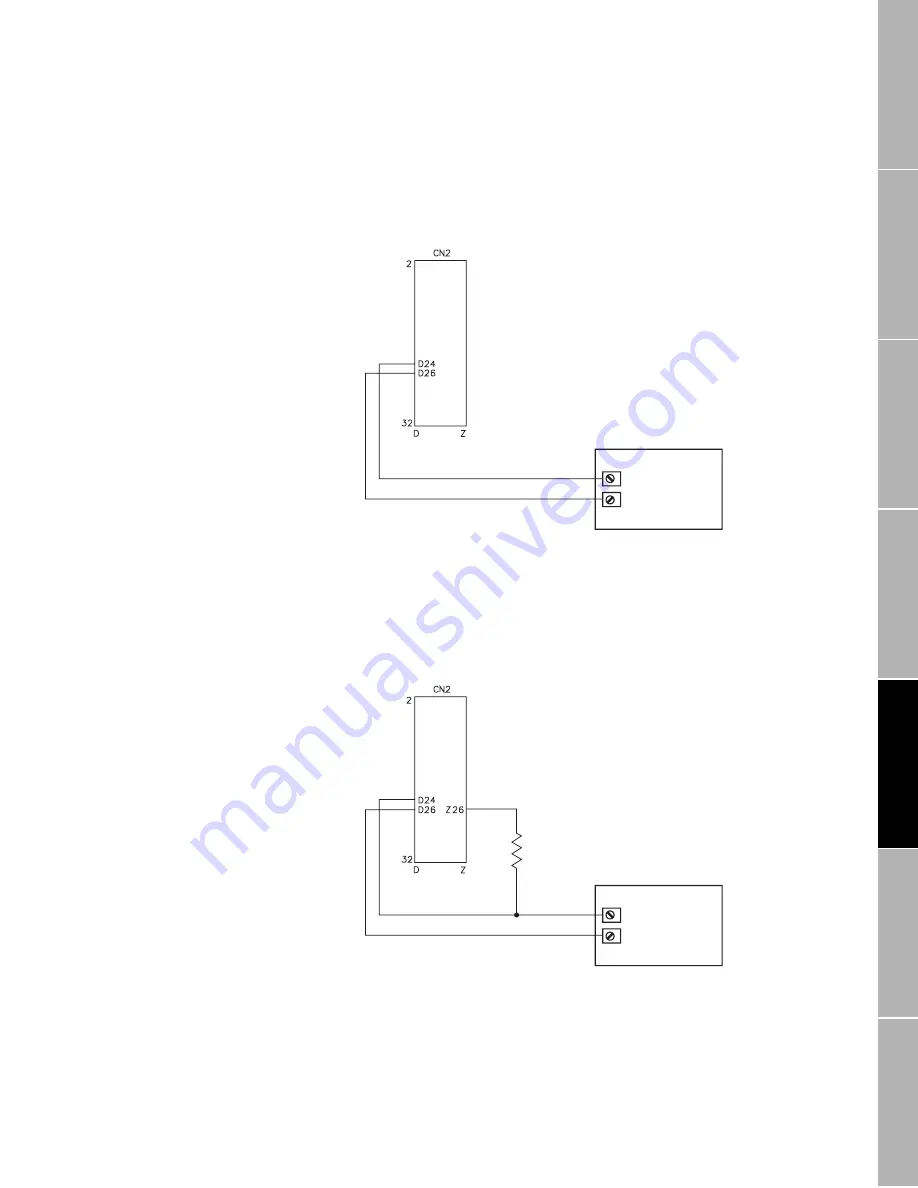
Default configuration
When the RFT9739 is shipped from the factory, the frequency/pulse
output is internally powered by an isolated 15-volt source via a 2.2 kohm
pull-up resistor. This internal current is limited to approximately 7 mA.
See Figure 5-5.
Figure 5-5.
Frequency/pulse output
wiring
Configuration for
increased current
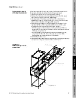
In some applications, it might be necessary to increase the current in the
frequency/pulse output circuit. See Section 5.2, page 25. For increased
current to the circuit, add a 1 to 3 kohm resistor across terminals
CN2-Z26 and CN2-D24, as illustrated in Figure 5-6.
Figure 5-6.
Frequency/pulse output
wiring for increased
current
PLC
or
pulse counter
FREQ+ (signal line)
RETURN (ground)
RFT9739
output terminals
PLC
or
pulse counter
1 to 3 kohm
resistor
FREQ+ (signal line)
RETURN (ground)
RFT9739
output terminals
Содержание Fisher Rosemount RFT9739
Страница 1: ...Model RFT9739 Rack Mount Transmitter Instruction Manual Version 3 Transmitters February 2000 ...
Страница 2: ......
Страница 4: ......
Страница 20: ...10 RFT9739 Rack Mount Transmitter Instruction Manual ...
Страница 26: ...16 RFT9739 Rack Mount Transmitter Instruction Manual ...
Страница 92: ...82 RFT9739 Rack Mount Transmitter Instruction Manual ...
Страница 100: ...90 RFT9739 Rack Mount Transmitter Instruction Manual ...
Страница 110: ...100 RFT9739 Rack Mount Transmitter Instruction Manual ...
Страница 112: ...102 RFT9739 Rack Mount Transmitter Instruction Manual ...
Страница 120: ...110 RFT9739 Rack Mount Transmitter Instruction Manual ...
Страница 122: ...112 RFT9739 Rack Mount Transmitter Instruction Manual ...
Страница 129: ......


