MICRO-EPSILON surfaceCONTROL 2500 Скачать руководство пользователя страница 20

Page 20

Operation of the Sensor

surfaceCONTROL 2500

6.4.3.3  Configuration

The network card settings should be adjusted to improve system performance when 
using Gigabit Ethernet cameras. Goal of the optimization is to minimize CPU usage and 
to avoid packet loss.

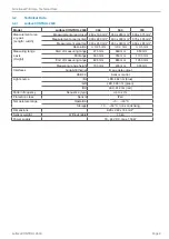
  Adjust the network card settings according to the following table:

Property

Value

Packet size/maximum transmission unit (MTU)

8228 bytes or greater

Interrupt moderation

Enable

Interrupt moderation rate

Extreme

Receive buffer

Maximum value configurable

Transmit buffer

256 bytes

The naming and setting options can vary depending on the network card used.

Standard packet size

The standard packet size of the cameras is 8228 bytes. The network card in the PC must 
support at least this packet size to make use of the full performance capability of the 
cameras.

Enabling jumbo frames

For optimal performance of the two cameras, jumbo frames should be enabled on the 
network card. Depending on the manufacturer and type of the network card, the setting 
is referred to as “Jumbo Frames” or “Jumbo Packets”. If this setting cannot be found, the 
network card does not support this feature and should not be used with the sensor.
Proceed as follows to enable the jumbo frames:

  Locate the network card used for the camera in the device manager or in a compa-

rable setting of your operating system.

  Go to the settings of the network card.
  Select the Jumbo Packet entry and set the value to 9014 bytes.
  Confirm the change with 

OK.

i

  After the change, an existing connection to the cameras is disconnected and re-

built.

6.5 

Operating Information

6.5.1 

Measuring Range

The measuring range of the sensors is factory-set. It is not possible to change the mea-
suring range by exchanging the lenses.
The area illuminated by the projector is relevant for the actual measuring range of the 
sensor. The cameras are arranged in such a way that both cameras capture the area 
illuminated by the projector within the complete measuring volume.
The measuring range in the Z-direction is trapezoidal due to the point-shaped light 
source of the projector and the fan-out over the lens.

Содержание surfaceCONTROL 2500

Страница 1: ...surfaceCONTROL 2500 360 surfaceCONTROL 2500 360 ST surfaceCONTROL 2500 500 surfaceCONTROL 2500 500 ST surfaceCONTROL 2500 720 surfaceCONTROL 2500 720 ST Operating Instructions surfaceCONTROL 2500...

Страница 2: ...INB Vision AG Brenneckestr 20 ZENIT Technology Park II 39118 Magdeburg Germany Tel 49 0 391 6117 300 Fax 49 0 391 6117 301 info inb vision com www inb vision com...

Страница 3: ...2 1 4 Image Data Transmission Gigabit Ethernet 15 5 2 2 surfaceCONTROL 2500 ST 16 5 2 2 1 General 16 5 2 2 2 Supply Voltage Power 16 5 2 2 3 Sensor Control USB 16 5 2 2 4 Image Data Transmission Giga...

Страница 4: ...A 1 Accessories and Spare Parts 24 A 1 1 Recommended Accessories Spare Parts 24 A 1 2 Optional Accessories 24 A 1 3 Drawings Mounting Adapters 25 A 1 3 1 X95 Dovetail Mounting Adapter 25 A 1 3 2 47 D...

Страница 5: ...The supply voltage must not exceed the specified limits Risk of injury Damage to or destruction of the sensor Avoid shocks and impacts to the sensor Damage to or destruction of the sensor The air inl...

Страница 6: ...act optical measurement of diffuse reflective surfaces quality monitoring and surface inspection The sensor must only be operated within the limits specified in the technical data see The sensor must...

Страница 7: ...Ambient pressure Atmospheric pressure Humidity Operation 20 80 non condensing Storage 10 90 non condensing 2 llumination The surfaceCONTROL 2500 sensor has an LED lighting unit with a high power LED o...

Страница 8: ...r with preinstalled software which are connected via a cable harness several fiber optic cables 3x2 only applies for the 2500 ST model The surfaceCONTROL 2500 sensor consists of two cameras a projecto...

Страница 9: ...25 mm 0 3 mm 0 5 mm Measuring range z axis Height Start of measuring range 475 mm 660 mm 950 mm Midrange 550 mm 760 mm 1100 mm End of measuring range 625 mm 860 mm 1250 mm Measuring range height 150...

Страница 10: ...ng range height 150 mm 200 mm 300 mm Interfaces Gigabit Ethernet LWL Image data output USB 2 0 LWL Sensor control Light source BL LED 462 nm blue GR LED 528 nm green RD LED 612 nm red Pattern frequenc...

Страница 11: ...ST sensor Sensor acceptance report Power supply cable 5 m long LEMO PushPull on sensor side 19 VDC table power pack CD with programs drivers sensor specific data and documentation Operating Instructi...

Страница 12: ...omputer mount it on a tripod or robot with the appropriate mounting adapters 5 1 1 Dimensions 250 3 9 85 313 1 12 3 139 5 47 0 151 6 6 142 5 5 6 0 250 3 9 85 313 1 12 3 82 3 23 82 3 23 0 70 5 2 78 1 5...

Страница 13: ...de of the sensor is used for unambiguous orientation of the adapter Mount the sensor to the mounting adapter ensuring full contact over the entire sur face The sensor and mounting adapter must not be...

Страница 14: ...ted to the connector housing A 2 pin LEMO PushPull connector is used on sensor side i For the power supply of the surfaceCONTROL 2500 sensor only the supplied pow er supply is to be used 5 2 1 3 Senso...

Страница 15: ...th screwed connections are used on sensor side The connection and tightening of the Ethernet cable to the sensor can be done by hand and does not require any tools Proceed as follows for this Carefull...

Страница 16: ...nected to the connector housing A 2 pin LEMO PushPull connector is used on sensor side i For the power supply of the surfaceCONTROL 2500 sensor only the supplied pow er supply is to be used 5 2 2 3 Se...

Страница 17: ...OM2 or the corres ponding cables from the accessories see A 1 1 Lay all connection cables in accordance with the generally applicable measuring tech nology regulations i e for example not directly ne...

Страница 18: ...ograms Various applications are provided for the operation of the sensor surfaceCONTROL Defmap3D for individual surface analysis supports all measurement tasks with surfaceCONTROL 2500 surfaceCONTROL...

Страница 19: ...ld be taken into account when selecting and configuring the network components 6 4 3 1 Components Due to the high data rate a high quality Gigabit Ethernet interface card is recommended for example In...

Страница 20: ...manufacturer and type of the network card the setting is referred to as Jumbo Frames or Jumbo Packets If this setting cannot be found the network card does not support this feature and should not be...

Страница 21: ...the surface of the test object If the test object contains design edges the sensor should be aligned as horizontally as possible to these The positioning of the sensor to the test object can be suppor...

Страница 22: ...ions of the projected light can also occur on grinding marks or small scratches on the surface This can result in inaccurate measured values Remedy can possibly be provided by adjusting the exposure o...

Страница 23: ...ry Within this period defective parts except for wearing parts will be repaired or replaced free of charge if the device is returned to INB Vision AG with shipping costs prepaid Any damage that is cau...

Страница 24: ...ble power pack 19 V Power supply for use with the sensor A 1 2 Optional Accessories Name Photo Description X95 dovetail mounting adapter Adapter for mounting on X95 profile Qioptiq or on tripod head w...

Страница 25: ...ons of the adapter are 95 mm x 95 mm x 15 mm A 1 3 2 47 Dovetail Mounting Adapter The 47 dovetail mounting adapter is used to mount the sensor on a quick release plate with a dovetail profile of size...

Страница 26: ...INB Vision AG Brenneckestr 20 ZENIT Technology Park II 39118 Magdeburg Germany Tel 49 0 391 6117 300 Fax 49 0 391 6117 301 info inb vision com www inb vision com X9751380 A032110HDR INB Vision AG...

Отзывы: