background image

Page 13

Initial Operation

FSC1/7, FSC1000

4.2 

Battery Pack

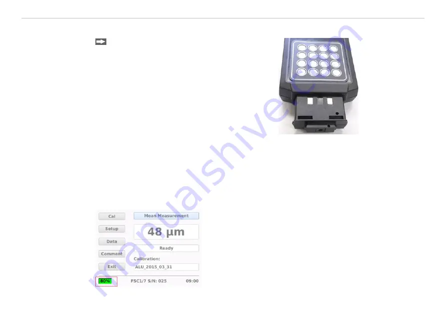
  Connect the battery to the controller with the con-

tacts on the upper side, see 

Fig. 5

.

i

  Charge the battery before initial operation. The bat-

tery must not be charged during measurements. 

Switch the controller off as defined before replacing 

the battery.

Replacing the battery: Press the latching mechanism on 

the battery together and pull it out.
Charging the battery: Connect the battery to the charger. 

The LED of the charger signalizes the charging process.

Fig. 5 Controller with 

battery

The state of charge of the battery is displayed on the controller screen, see 

Fig. 6

. The display will light up 

green with a state of charge from 20% to 100% and red for less than 20%. The controller will display a warn-

ing message when the remaining capacity is 10%. The controller will switch off automatically when the status 

display reaches 0%.
The status display for the battery becomes visible approximately one minute after the controller is switched 

on.

Fig. 6 Battery state of charge

Содержание FSC1/7

Страница 1: ...Operating Instructions FSC1 7 FSC1000 PReliminary...

Страница 2: ...nigbacher Strasse 15 94496 Ortenburg Germany Phone 49 0 8542 168 0 Fax 49 0 8542 168 90 email info micro epsilon com www micro epsilon com Layer thickness measuring device for insulators on metal and...

Страница 3: ...packing Included in Delivery 10 3 2 Storage 10 4 Initial Operation 11 4 1 Dimensional Drawings 11 4 2 Battery Pack 13 5 FSC1 7 and FSC1000 Operation 14 5 1 Switch on Phase Warm up 14 5 2 General Contr...

Страница 4: ...ement Data 30 5 8 3 Managing Measurement Data 31 5 8 4 Saving Exporting Measurement Data 31 5 9 Ending the Measuring Program Switching off the Controller 33 6 Liability for Material Defects 33 7 Clean...

Страница 5: ...a tip for users Measurement Indicates hardware or a software button menu 1 2 Warnings Avoid shocks and impacts to the sensor Damage to or destruction of the sensor Avoid exposure of sensor and control...

Страница 6: ...als and Part 15 Class C Low Power Communication Device Transmitter with the US Federal Communications Commission FCC This device complies with part 15 of the FCC Rules Operation is subject to the foll...

Страница 7: ...used to measure the thickness of paint and other electrically insulating layers on substrates such as carbon fiber reinforced plastics CFRP CFRP with metallic lightning protection and metals The syst...

Страница 8: ...f dielectric layers on CFRP CFRP with lightning protection metals and conductive or weakly conducting materials The device includes a sensor handheld module and a controller control and display module...

Страница 9: ...lightning protection metals Power supply NiMh battery Temperature Operation 10 40 C 50 104 F Storage 0 45 C 32 113 F Dynamic tilt prevention ON OFF Parameters Statistical functions with recording and...

Страница 10: ...on foils 1 Operating instructions and test certificate 1 Carry case Carefully remove the components of the measuring system from the packaging and ensure that the goods are forwarded in such a way tha...

Страница 11: ...Page 11 Initial Operation FSC1 7 FSC1000 4 Initial Operation 4 1 Dimensional Drawings 68 2 68 123 4 84 48 1 89 54 2 13 Fig 3 Sensor dimensions in mm inches Active measuring surface sensor...

Страница 12: ...Page 12 Initial Operation FSC1 7 FSC1000 128 5 04 43 1 96 230 9 06 238 9 37 Fig 4 Controller dimensions in mm inches...

Страница 13: ...e battery Connect the battery to the charger The LED of the charger signalizes the charging process Fig 5 Controller with battery The state of charge of the battery is displayed on the controller scre...

Страница 14: ...es sufficient time to adapt to the ambient temperature LED On USB Sensor On button 5 2 General Controller Operation The controller can be operated using the touchscreen or the keyboard The touchscreen...

Страница 15: ...sensor is established when the sensor s serial number is displayed at the bottom of the screen see Fig 8 The device is ready for operation If a connection to the sensor cannot be established this is...

Страница 16: ...ment by pressing keys 1 2 or 3 on the controller Both Start measurement by pressing the button on the sensor or keys 1 to 3 Measure count 1 2 3 4 5 All three parameters ensure repeatable measurement r...

Страница 17: ...Page 17 FSC1 7 and FSC1000 Operation FSC1 7 FSC1000 Gray highlighted fields allow for a selection Fig 10 Setup menu...

Страница 18: ...t table Manage Calibrations Manage delete existing adjustment tables New Calibration Create new adjustment table The measuring system can be calibrated on various sub strate materials Potential substr...

Страница 19: ...Fig 12 Data set selection Fig 13 Data set details Select the desired file and confirm with the Load button Once an adjustment is loaded a window will appear with the basic information regarding the a...

Страница 20: ...Managing Adjustment Tables You can manage existing data sets in the Manage Calibration submenu Possible options Del Deletes the selected data set Load Loads the selected data set ESC Back to measurin...

Страница 21: ...r recertify the foils after the fact Switch to the New Calibration menu The adjustment can be started when Ready is displayed in the status window Fig 15 Adjustment ready You must select at least two...

Страница 22: ...ge of max 100 to 150 m over the entire measuring range Make sure that the measuring area of the sensor the calibration foil and the measur ing point are clean Place the second calibration foil on the...

Страница 23: ...asure count Measure delay and Max delta in the setup these settings will also be used for the adjustment i To carry out the adjustment set the Max delta parameter to the smallest possible value and se...

Страница 24: ...List of support points during an adjustment You can change a selected support point using the Edit button Use the ESC button to cancel an adjustment series the system will return to measuring mode Us...

Страница 25: ...e deviation delete the support point and recreate it see Fig 19 Fig 21 Test result Use the Save Calibration Data field to assign a name to the adjustment data set Then press Save Fig 22 Name assignmen...

Страница 26: ...s the button on the sensor or keys 1 to 3 on the controller The measurement will start 300 ms after you release the measuring button Fig 23 Measurement preparation Fig 24 Display of measurement result...

Страница 27: ...sted measuring range If the individual measurements have a deviation that is greater than the default Setup Max Delta menu the measurement was not successful The system will generate the message Diff...

Страница 28: ...alyze the measurement data the mean value and the standard deviation are determined for the measured values within the values listed Switch to the Mean Measurement menu on the start screen Last Curren...

Страница 29: ...cted and removed from the list in the log file but they are not used however for the statistical data set The measured values displayed in the statistic and overview are used for the statistics functi...

Страница 30: ...ta menu on the screen Fig 31 Measurement file selection 2018_07_10_000 Mean 104 m SD 18 19 m Count 3 Min 90 m Max 130 m 12 16 49 129 m 12 16 05 131 m 12 17 38 130 m 12 17 46 93 m 12 17 54 90 m up down...

Страница 31: ...ted file Load Opens the selected file with the data viewer see Chap 5 8 2 Esc Returns to the start screen Fig 33 Managing the measuring files 5 8 4 Saving Exporting Measurement Data You can use the Sa...

Страница 32: ...ion FSC1 7 FSC1000 After the data has been successfully saved this is displayed Fig 34 Saving the measurement data If no data carrier is connected or it is not recognized you will see a message Fig 35...

Страница 33: ...erial defects is 12 months from delivery Within this period defective parts except for wearing parts will be repaired or replaced free of charge if the device is returned to MICRO EPSILON with shippin...

Страница 34: ...lt cannot be clearly determined always send the complete measuring system to MICRO EPSILON MESSTECHNIK GmbH Co KG K nigbacher Strasse 15 94496 Ortenburg Germany Tel 49 0 8542 168 0 Fax 49 0 8542 168 9...

Страница 35: ...Ver 2 Ver 2 1 Ver 3 Digia Qt LGPL Exception version 1 1 Raspbian Jessie Raspbian Kernel 4 4 34 v7 GNU General Public License GPL 2 GNU GPL plus the GCC Runtime Library Exception ICU License ICU 1 8 1...

Страница 36: ...N MESSTECHNIK GmbH Co KG K nigbacher Str 15 94496 Ortenburg Germany Tel 49 0 8542 168 0 Fax 49 0 8542 168 90 info micro epsilon com www micro epsilon com X9751382 A051109SWE X975382 A05 MICRO EPSILON...

Отзывы: