


Instruction Manual MIC type EC-912
Revision no.4
21 / 38
The smoke density can be defined in terms of X as follows:
CHO
CH
CHO
I
I
I
X
−
=
(0
X
1)
(4.1.1)
I
CHO
[A] is the chamber quiescent current (clean air)
I
CH
[A] is the chamber current when smoke is present
It appears from eq. 4.1.1 that X = 0 in clean air and X = 1 when the smoke density is infinite.
Smoke density can also be expressed in Y-values which are related to the X-values as follows [1]:
X
1
X
2
X
Y
−
−
=
(4.1.2)
The Y-value can also be transferred to a value related to a chamber voltage of 20 V. This Y
20
-value is
related to the Y-value as follows:
20
U
Y
Y
c
20
=
(4.1.3)
The advantage of expressing the smoke density in terms of Y and Y
20
-values is that these values are
proportional to the number of smoke particles per unit volume.
Besides smoke density, the X, Y, and Y
20
-values depend on the design of the ionization chamber and
a number of environmental parameters.
So, the readings obtained from different ionization chamber configurations cannot be compared unless
the correction factor for the chambers is known, e.g. from calibration.
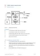
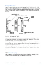
Measuring Ionization Chamber (MIC)
Ionization chamber design
The MIC has a parallel plate electrode configuration in which the radioactive source (Am 241) is part
of one of the electrodes. This configuration provides a measuring volume in which the ionization is
uniform and approx. parallel to a constant electrical field.
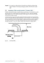
The air is sucked through the chamber in order to reduce wind dependence, but the air in the
measuring volume between the electrodes is stationary since the sucked air flows in a duct which is
separated from the measuring volume by means of a wire mesh. Smoke is transferred from the air
flow to the measuring volume by diffusion.


