


General
This document describes the installation requirements for a single Enigma panel.
This document is work in progress and still very incomplete. Please check on our website
for any updates to the Enigma installation documentation.
Electrical installation
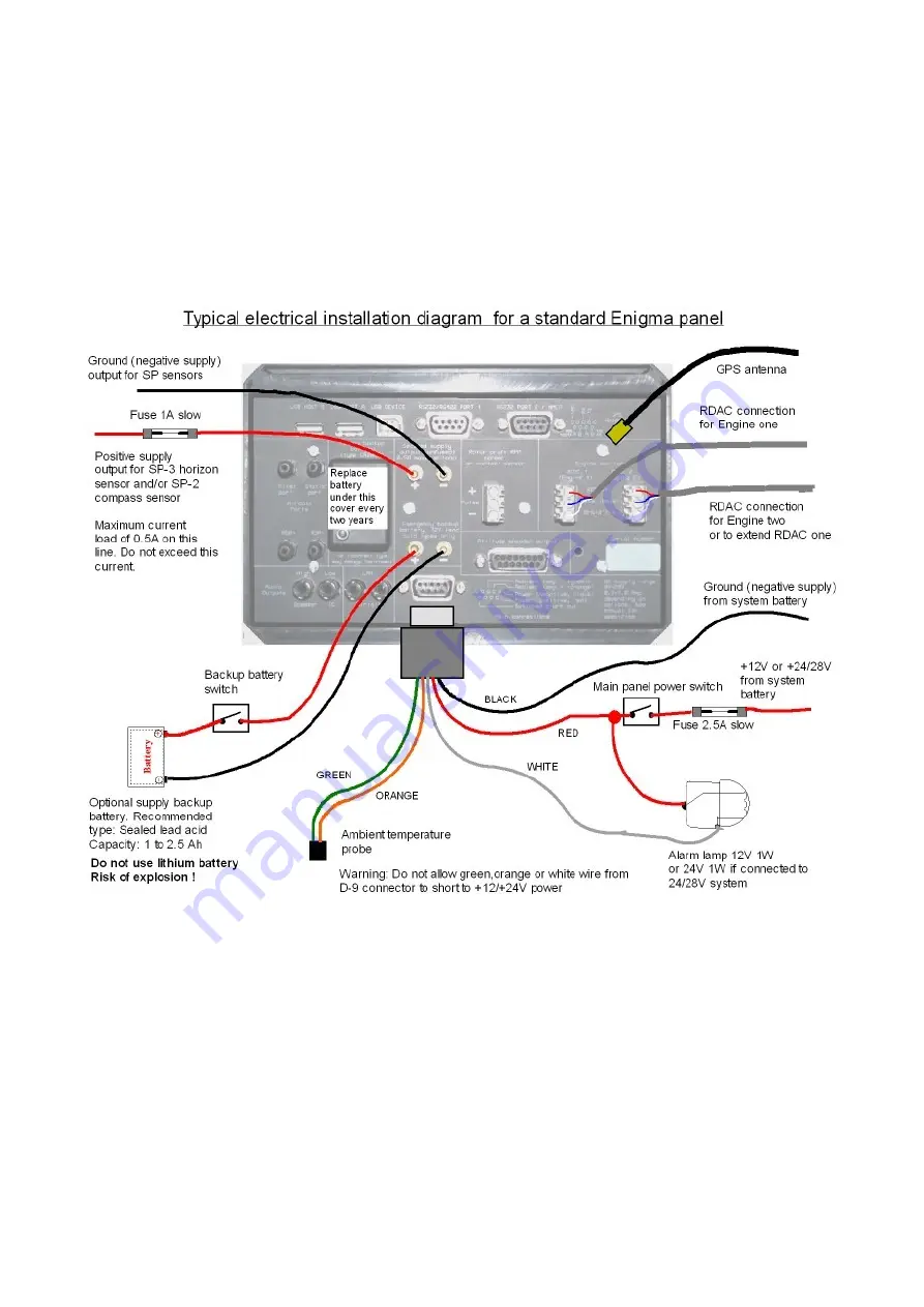
This image shows typical wiring for an Enigma panel.
In this case a small backup battery is used. Note that two power switches are required.
One power switch for the main incoming 12 or 24 V feed (switch in positive supply lead),
another for the backup battery.
In flight, both switches would be “on” allowing the charging of the backup battery.
Preflight check would involve switching main power on, then battery power on. Check of
battery power would involve switching main power off and verifying that Enigma continues
to operate. Voltage on the backup battery should be measured by means of the backup
voltage readouts which can be placed on any display.
In this case the secured supply output is used to power a SP-3 or SP-2 horizon sensor
and/or compass. This supply will draw from the backup battery in case of main power fail.
Please note that it is not permissible to connect other high current users to this supply