Quick Start
3
86-86000-03 B00
STEP 4 Systems Connections
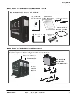
EX RT Transformer Module Quick Start
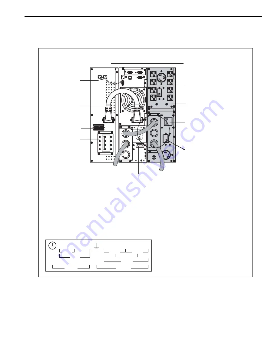
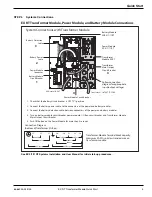
EX RT Transformer Module, Power Module, and Battery Module Connections
System Connections with Transformer Module
AC Normal INPUT
Transformer OUTPUT TO LOAD
Battery Module
EXB 5/7/11RT
Power Module
EX 5/7/11 RT
Transformer
Module EX RT
Transformer
Main Output
Circuit Breaker
Follow connection
diagram for appropriate
input/output voltages.
Connection Diagram
(bottom of Transformer I/O Box)
L3 L2 L1 Lb Ld N Lc La
208Vac
240Vac
AC Input
120Vac
208Vac
AC Output
120Vac
240Vac
Transformer Module Terminal block capacity:
maximum 4 AWG solid or stranded wire on
transformer module.
1. Check that the battery circuit breaker is OFF (“0”) position.
2. Connect the battery power cable to the connectors of the power and battery modules,
3. Connect the battery detection cable between connectors of the power and battery modules.
4. Turn on battery module circuit breaker, power module, I/O Box, circuit breaker, and Transformer Module
Main Output Circuit Breaker.
5. Push ON button on the Power Module for more than 3 seconds.
Battery Module
Circuit Breaker
Battery Power
Cable
Power Module
Connector
Battery Detection
Cable
1
2
3
Power Module Circuit Breaker
4
4
See EX 5/7/11RT Systems Installation and User Manual for initial start-up procedures.


