F EC-820K Instruction Afanua/
CII'Fi/ter
30. Insert RIO into its mounting holes so the resistor body rests against the
board. Solder in place and trim the leads.
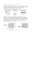
31. Locate resistor R11. This is 24.3K resistor (red-yellow-orange-red-
brown). Carefully bend the leads close to the resistor body as in Step #I1.
32. Insert RI 1 into its mounting holes so the resistor body rests against the
board. Solder in place and trim the leads.
33. Locate resistor R12.
This is 24.3K resistor (red -yellow-orange-red-
bro,yn). Carefully bend the leads close to the resistor body as in Step
#11.
34. Insert R12 into its mounting holes so the resistor bod_N rests against
the board. Solder in place and trim the leads.
35. Locate resistor R13. This is 24.3K resistor (red-yellow-orange-red-
brown). Carefully bend the leads close to the resistor body as in Step #11.
36. Insert R13 into its mounting holes so the resistor body rests against the
board. Solder in place and trim the leads.
37. Locate resistor R14 This is 24.3K resistor (red-yellow-orange-red-
brown). Carefully bend the leads close to the resistor body as in Step #11.
38. Insert R14 into its mounting holes so the resistor body rests against the
board. Solder in place and trim the leads. Save the excess trimmed pieces of
resistor lead. You will need it later.
39. Locate a G" length piece of insulated wire. and cut piece 1 1/4" long off
of it
40. Using the wire strippers, remove 1/4" of insulation from each end of the
1 1/4" wire.
42. Solder the 1 1/4" wire in place at JNIP2 and trim the excess wire.
43. Locate the pieces of excess resistor lead you saved back in step #38.
44. Install the excess lead in the holes located at JNIP I on the circuit
board. Solder in place and trim the excess lead.
41. Insert the bare ends of the 1 1/4" wire into the holes on the circuit
board located at JMP2. Please refer to the section titled "Parts Placement".
Figure 1 for the location of JNIP2.


