background image

INSTRUCTION MANUAL

CAUTION: Read All Instructions Before Operating Equipment

MFJ ENTERPRISES, INC.

300 Industrial Park Road
Starkville, MS 39759 USA

Tel: 662-323-5869 Fax: 662-323-6551

COPYRIGHT

2004 MFJ ENTERPRISES, INC.

C

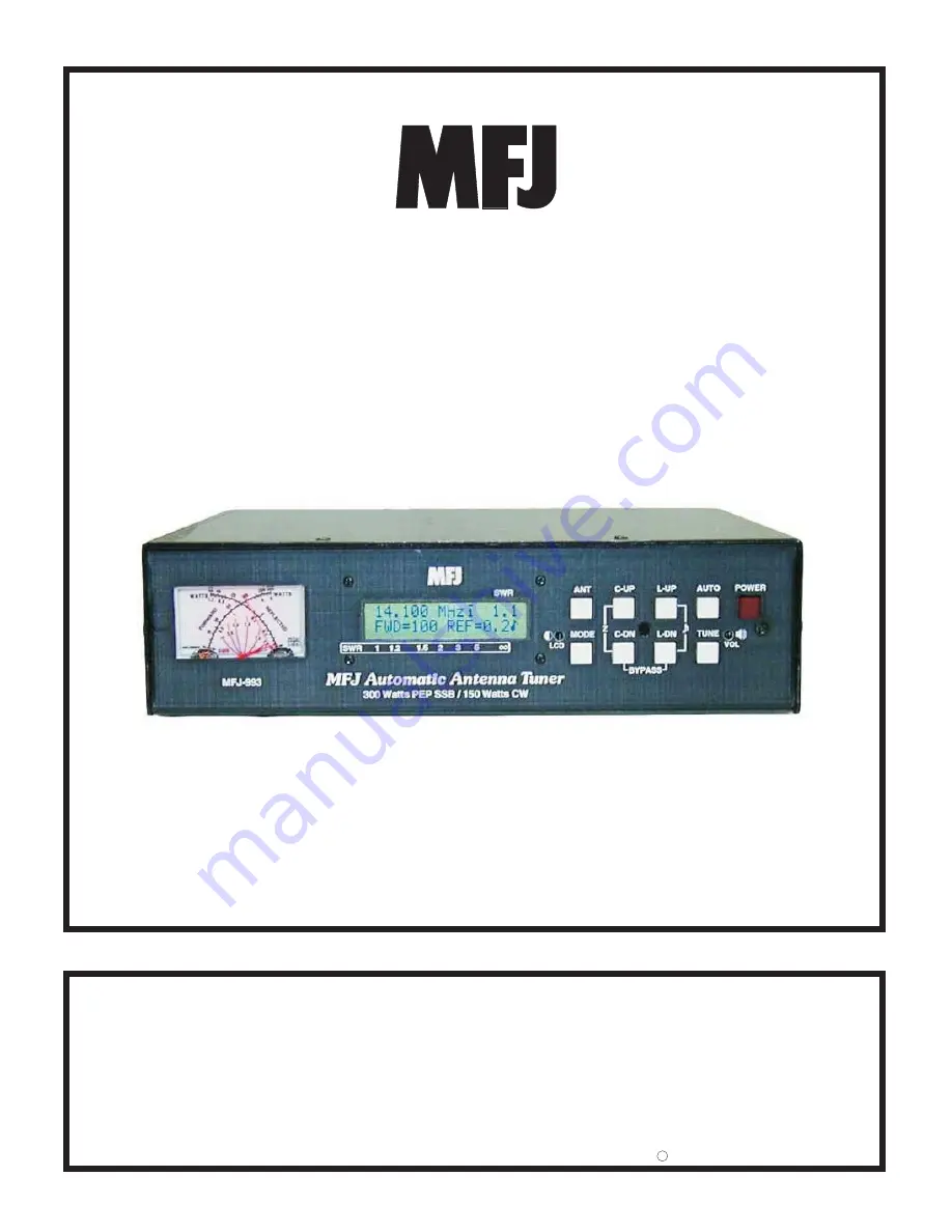
Model MFJ-993

VERSION 1C

IntelliTuner

Automatic Antenna Tuner

TM

Содержание MFJ-993

Страница 1: ...tructions Before Operating Equipment MFJ ENTERPRISES INC 300 Industrial Park Road Starkville MS 39759 USA Tel 662 323 5869 Fax 662 323 6551 COPYRIGHT 2004 MFJ ENTERPRISES INC C Model MFJ 993 VERSION 1C IntelliTuner Automatic Antenna Tuner TM ...

Страница 2: ......

Страница 3: ... UP and C DN Buttons 4 L UP and L DN Buttons 5 AUTO Button 5 TUNE Button 5 VOL Control 5 POWER Button 5 Back Panel 6 Power 6 Remote Port 6 Radio Interface 6 Transmitter 7 Balanced Line 7 Wire 7 Ground 7 Antenna 1 7 Antenna 2 7 Installation 8 SWR Wattmeter 8 THE MENUS Main Mode Menus 9 Digital Wattmeter Menu 9 Power Bar Meter Menu 10 SWR Bar Meter Menu 10 L Network Menu 10 Tuner Indicators 13 Anten...

Страница 4: ...Location 19 Matching Problems 19 APPENDICES Resetting the Tuner 21 Factory Defaults 21 Delete Antenna Memory 22 Total Reset 22 Self Test 22 Power Down Circuit Test 23 Relay Test 24 Firmware Version Number via Meter 24 Setting the Speaker Volume 24 Wattmeter Calibration 25 SWR Bridge Calibration 25 Frequency Counter Calibration 26 In Case of Difficulty 27 Technical Assistance 27 List of Accessories...

Страница 5: ...ure 8 SWR Bar Meter 10 Figure 9 Mode Button Flow Chart and Button Action 11 Figure 10 Main Mode Menus Display 12 Figure 11 Power On Operations 21 Figure 12 MFJ 993 Circuit Block Diagram 28 TABLES Table 1 Memory Resolution 14 Table 2 Meter Needle Stationary Codes 17 Table 3 Meter Needle Bounce Codes 18 Table 4 Failure Messages 23 ...

Страница 6: ...MFJ 993 IntelliTuner Automatic Antenna Tuner Instruction Manual 2003 2004 MFJ Enterprises Inc iv THIS PAGE IS LEFT BLANK INTENTIONALLY ...

Страница 7: ...ns can learn and remember more than a thousand frequencies and tuner settings When you key your transmitter MFJ s InstantRecallTM checks its memory to see if you have operated that frequency before If so tuning is instantaneous and you re ready to operate If not MFJ s IntelliTuneTM algorithm based on MFJ s famous SWR Analyzer technology kicks in It measures the complex impedance of your antenna Ne...

Страница 8: ...as Built in 4 1 current balun for balanced line antennas Optional remote control Optional radio interface for compatible radios Specifications Impedance matching range 6 to 1600 ohms Minimum power for tuning 5 watts Maximum power while tuning 100 watts with foldback 20 watts without foldback RF power limit 300 watts PEP SSB 150 watts CW Frequency range 1 8 to 30 MHz continuous coverage Frequency c...

Страница 9: ... BALANCED LINE binding posts and connect a jumper between the other two posts as indicated 4 Connect your ground connection to the GROUND post 5 Press the POWER button to turn on the MFJ 993 tuner Place the ANT button in the out position to select antenna 1 Press the AUTO button in to select semi automatic mode 6 Key your transmitter to output a carrier of 10 watts CW FM or AM 7 Press and hold the...

Страница 10: ...er to Figure 10 for descriptions of the various displayed information LCD Contrast Control A trimpot control that adjusts the contrast of the LCD display Use a small flat blade screwdriver and turn clockwise to increase contrast ANT Button Used to select the antenna to tune Button out selects Antenna 1 button in selects Antenna 2 The Antenna indicator on the main display indicates the selected ant...

Страница 11: ...ond to bypass the tuner RF from the transmitter goes directly to the antenna with no matching Press and hold TUNE for 0 5 to 2 seconds to start the automatic tuning process The transmitter must be keyed first with at least 5 watts of power When the SWR is already below the target SWR pressing TUNE will fine tune the match for a lower SWR if possible StickyTune allows for one handed tuning operatio...

Страница 12: ...J 993RC duplicates all the front panel buttons except POWER and MODE In addition there are two LEDs on the remote control The red Tuning LED lights to indicate tuning is in progress and the green SWR LED lights when the SWR is below the target SWR Note To use the remote control both the ANT and AUTO buttons on the automatic tuner must be pressed in otherwise Antenna 1 and Automatic mode are select...

Страница 13: ...d AH 4 tuners Push and hold the radio s TUNER button for two seconds to start the tuning process Push TUNER quickly to bypass the tuner Pin 1 Key connects to the Tip of 3 5 mm Stereo Phone Plug Pin 2 Start connects to the Ring of 3 5 mm Stereo Phone Plug Pin 3 13 8V connects to the Center Pin of Power Plug Pin 4 Ground connects to the Sleeves of both 3 5 mm Stereo Phone Plug and Power Plug Figure ...

Страница 14: ...he antenna s to the tuner as follows Coaxial feedlines to the SO 239 connectors labeled ANTENNA 1 and or ANTENNA 2 Random wire or single wire line antennas should be connected to the WIRE binding post on the back of the tuner and remove the jumper wire Note the back panel warning Do not connect WIRE and ANTENNA 1 at same time When a single wire antenna is connected it becomes ANTENNA 1 Note Route ...

Страница 15: ...d by observing the point where the forward and reflected power needles cross on the red curved scales across the center of the meter No cumbersome or time consuming SWR sensitivity adjustments are required with this meter Figure 6 shows an SWR of approximately 2 0 The meter also indicates various operational states of the tuner Refer to Meter Codes and Audible Beeps on page 16 for more details The...

Страница 16: ...r about one second so that you can more easily read the meter This function can be turned ON and OFF in the Peak Hold setup mode 0 25 50 75 100 Pwr 300 Figure 7 Power Bar Meter SWR Bar Meter Menu Shows the frequency SWR and SWR bar meter A SWR scale is printed just below the display on the front panel The 15 segment SWR bar meter indicates SWR of 1 0 1 1 1 2 1 3 1 4 1 5 1 6 1 7 1 9 2 0 2 4 2 5 2 9...

Страница 17: ...TTON ACTION Press to increase both capacitance and inductance C UP L UP MODE AUTO ANT C UP L UP C DN L DN TUNE POWER Press less than 0 5 second to bypass the tuner press and hold for 0 5 to 2 seconds to start the tuning process press and hold for more than two seconds to toggle the StickyTune on and off Press in to select semi automatic mode out to select automatic mode Press to decrease inductanc...

Страница 18: ...ance value when on antenna side Capacitance value when on transmitter side Appears when Antenna 1 is selected Appears when Antenna 2 is selected Appears when Memory is ON Appears when IntelliTune is ON Appears when in Semi Auto mode Appears when StickyTune is ON Appears when LC Limit is OFF Appears when SWR Beep is ON Appears when Meter Range is 300 watts Appears when Auto Range is ON 25 16 17 18 ...

Страница 19: ...and hold the MODE button for two seconds The setup menu that will display is the one that was last used When finished press the MODE button for two seconds to go back to the main mode for normal operation The tuner goes into protective bypass mode in the setup mode and restores the matching network after exiting the setup mode If no button is pressed for more than eight seconds the tuner automatic...

Страница 20: ...han 30 watts or reflected power greater than six watts automatically sets the meter to the high power range Forward power less than 25 watts and reflected power less than four watts automatically set the meter to the low power range Refer to Figure 10 for the on screen Meter Range indicators Default is 300 watts range Shortcut Press both TUNE and C DN buttons simultaneously to toggle Auto Range on...

Страница 21: ...of calculation If for any reason this function can be turned off Refer to Figure 10 for the on screen IntelliTuneTM indicator Default is ON SWR Beep Menu Turns the aural SWR meter on and off The aural meter is a series of one to five beeps where one beep indicates SWR of 1 5 or less two beeps indicate SWR of 1 6 to 2 0 three beeps indicate SWR of 2 1 to 2 5 four beeps indicate SWR of 2 6 to 3 0 an...

Страница 22: ... for one click past it Manual tuning of inductance is similarly accomplished using L UP and L DN Since the capacitance and inductance are interdependent some back and forth between the two may be needed just as in a conventional tuner with knobs Once you are familiar with this process you will learn how to match certain antennas and frequencies Pressing C UP and C DN buttons simultaneously moves t...

Страница 23: ...ugh power is applied for tuning less than 5 watts the display will flash INCREASE POWER three times and QRO dah dah di dah di dah dit dah dah dah will be sent on CW Increasing the input power above five watts ends this message When input power is too high the tuner enters a self protection mode The tuner will not allow any of its relays to change This feature is to prevent damage to your tuner If ...

Страница 24: ...ner to the outdoor ground The antenna feed wire should be adequately insulated to prevent arcing or accidental contact CAUTION For operator safety a good outside earth ground or water pipe ground should always be installed and connected to the case of the MFJ 993 Make certain the safety ground also connects to the transmitter and other station accessories A wing nut post marked GROUND is provided ...

Страница 25: ...gh impedance and the transmission line is a multiple of a half wavelength The half wavelength line repeats the very high antenna impedance at the tuner Incorrect feedline and antenna lengths can make an otherwise perfect antenna system very difficult or impossible to tune One example where this problem occurs is on 80 meters when an odd quarter wave 60 to 70 feet open wire line is used to feed a h...

Страница 26: ... dipole 34 40 90 102 or 160 172 feet Avoid 66 135 190 ft 40 meters dipole 42 52 73 83 112 123 or 145 155 feet Avoid 32 64 96 128 ft Some slight trimming or adding of feedline may be necessary to accommodate the higher bands WARNING To avoid problems a dipole antenna should be a full half wave on the lowest band On 160 meters an 80 or 40 meters antenna fed the normal way will be extremely reactive ...

Страница 27: ...R POWER POWER POWER POWER POWER POWER POWER POWER Press and hold to output audio for volume adjustment POWER L UP C UP L UP Figure 11 Power On Operations Important The radio interface cable must be disconnected from the tuner if the radio power is off before performing any of the following power on operations Resetting the Tuner Each time the tuner is powered off the microprocessor saves all memor...

Страница 28: ...er that the selected antenna memory will be lost Total Reset To erase both antenna memories and reset to factory defaults press and hold down the TUNE C DN and L DN buttons while turning the power on A confirmation message TOTAL RESET will display Press the YES C UP button to delete both antenna memories and reset factory defaults RESET will display and both meter needles go to full scale or press...

Страница 29: ...f the unit is okay a repetitive message PASS will be displayed and sent as Morse code di dah dah dit di dah di di dit di di dit and both meter needles will go to full scale If there is a problem a failure message will be displayed and sent also the forward needle will bounce and the reflected needle mark indicates the failure 10 Once you have confirmed that the audio is okay turn the unit off Fail...

Страница 30: ...ay The C UP L UP C DN and L DN buttons corresponding to the position of the relay numbers on the display are used to toggle each relay on and off Press button to engage the relay and release it to disengage the relay Listen for relay clicks Press the TUNE button to proceed to the next group of four relays There are 19 relays in the tuner Repeat the above procedure to test all the relays Normal ope...

Страница 31: ... set the reflected needle to the 20 watt mark 7 Press the TUNE button to end calibration 8 Turn off the tuner power and secure the cover back onto the tuner SWR Bridge Calibration To calibrate the SWR Bridge you will need a transmitter capable of 100 watts output a precise calibrated wattmeter a 50 ohm dummy load three 50 ohm SO 239 coax cables a Phillips screwdriver and a tuning tool or small fla...

Страница 32: ...onnect your transmitter to the TRANSMITTER connector and connect your antenna to the appropriate antenna connector on the tuner Frequency Counter Calibration To calibrate the frequency counter you will need a transmitter a 50 ohm dummy load two 50 ohm SO 239 coax cables a Phillips screwdriver and a tuning tool or small flat blade screwdriver WARNING Do not touch anything inside the tuner during op...

Страница 33: ... please read Grounding Hints on page 18 and Antenna System Hints on page 19 Technical Assistance If you have any problem with this unit first check the appropriate section of this manual If the manual does not reference your problem or your problem is not solved by reading the manual you may call MFJ Technical Service at 662 323 0549 or the MFJ Factory at 662 323 5869 You will be best helped if yo...

Страница 34: ...ock Diagram Transmitter Antenna 2 Antenna 1 Remote Port Radio Interface Balanced Line Wire Impedance Sensor SWR Sensor Frequency Counter Memory Microcontroller Relay Drivers Ground SWR Wattmeter Push Buttons LCD Display Speaker User Interface Contrast Volume 4 1 Current Balun Inductors 0 24 uH Capacitors 0 3900 pF Z L Network ...

Страница 35: ...rvice Department at 662 323 0549 or the MFJ Factory at 662 323 5869 4 This warranty does not apply to kits sold by or manufactured by MFJ Enterprises Inc 5 Wired and tested PC board products are covered by this warranty provided only the wired and tested PC board product is returned Wired and tested PC boards installed in the owner s cabinet or connected to switches jacks or cables etc sent to MFJ...

Страница 36: ...MFJ 993 Manual Version 1C Printed In U S A 03 2004 300 Industrial Park Road Starkville MS 39759 MFJ ENTERPRISES INC ...

Отзывы: