INSTRUCTION MANUAL
CAUTION: Read All Instructions Before Operating Equipment
MFJ ENTERPRISES, INC.
300 Industrial Park Road
Starkville, MS 39759 USA
Tel: 662-323-5869 Fax: 662-323-6551
COPYRIGHT 2014 MFJ ENTERPRISES, INC.
C
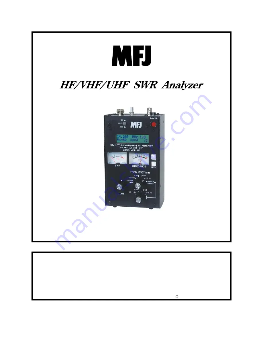
Model MFJ-269C
VERSION 1A
Страница 1: ...UTION Read All Instructions Before Operating Equipment MFJ ENTERPRISES INC 300 Industrial Park Road Starkville MS 39759 USA Tel 662 323 5869 Fax 662 323 6551 COPYRIGHT 2014 MFJ ENTERPRISES INC C Model...
Страница 2: ...ER SAVING 6 3 0 MAIN MENU AND DISPLAY 7 3 1 GENERAL CONNECTIONS 7 3 2 POWER UP DISPLAY 7 3 3 MAIN MEASUREMENT MODES LF HF VHF 0 53 230 MHZ 8 3 4 FREQUENCY CONTROL 9 4 0 MAIN OR OPENING MODE 10 4 1 GEN...
Страница 3: ...7 0 TESTING AND TUNING STUBS AND TRANSMISSION LINES 31 7 1 TESTING STUBS 31 7 2 VELOCITY FACTOR OF TRANSMISSION LINES 32 7 3 IMPEDANCE OF TRANSMISSION LINES OR BEVERAGE ANTENNAS 33 7 4 ADJUSTING TUNER...
Страница 4: ...ion signal source and frequency counter Operating frequency extends from 0 53 to 230 MHz in nine overlapping bands with extended SWR measurement from 415 to 470 MHz LF coverage may be adjusted to cove...
Страница 5: ...269C or any small handheld unit would drive the price far beyond the reach of most hobbyists As an alternative we use broadband detectors that provide accurate measurements at a much lower cost The o...
Страница 6: ...were factual The MFJ 269C is designed to avoid such errors by displaying an on screen warning Z 1500 anytime data falls outside the unit s accurate measurement range 2 0 POWER SOURCES This section des...
Страница 7: ...mper fits over two of three adjacent pins see detailed instructions below The plug must be properly positioned for the type of cell you plan to use AA rechargeable or AA non rechargeable 2 3 Rechargea...
Страница 8: ...ue operating However measurements may not be reliable when operating the analyzer with insufficient supply voltage 2 6 Sleep Mode Power Saving Typical current drain for the MFJ 269C is around 150 mA f...
Страница 9: ...ibed in section 2 0 Please read the power source section carefully before attempting to operate the analyzer Improper voltage application the wrong battery charger setting or reversed polarity could p...
Страница 10: ...the load s series resistive component and Xs shows the load s series reactive component In this function the analog SWR and Impedance Meters Z are also activeated 2 Coax Loss Pressing Mode once brings...
Страница 11: ...a 2 mm hex tuning wand readjust inductor L12 while watching the frequency display 2 UHF Operation UHF coverage is broken into two bands To measure UHF SWR 415 490 MHz first press in the UHF switch lo...
Страница 12: ...m 3 Coaxial Cable Always use good quality 50 ohm cable and connectors when making SWR measurements Contaminated mismatched or damaged cable will introduce significant error 4 Calibration Plane When ma...
Страница 13: ...rolled amount 360 degree phase rotation 2 Electrical Half Wavelengths of Cable Installing a half wavelength of cable between the load and the analyzer will rotate phase a full 360 degrees so that no a...
Страница 14: ...Installing a balun is good engineering practice and always worth doing 7 Defective Cable Your coax may not really be 50 ohms Kinks water ingress oxidation corrosion bad connectors improper manufacturi...
Страница 15: ...g the Mode switch The top line of the working display shows the Frequency in MHz and the Capacitive Reactance Xc of the DUT at that specific frequency The lower line displays the computed Capacitance...
Страница 16: ...cations the frequencies will be far below it In addition to the display the analyzer s Impedance meter displays the reactance X in ohms of the capacitor 4 5 Inductance Function 4 Access the Inductance...
Страница 17: ...uency Counter mode is the final Main Mode function To access the counter from the opening menu press Mode four times or if already in the Main menu step through it until the Freq Counter screen appear...
Страница 18: ...pedance conditions System resolution is limited mostly by diode linearity calibration stability and external noise or signals While we have attempted to make this unit as accurate as possible most for...
Страница 19: ...VOLTAGES OR RF SIGNALS TO THE ANTENNA CONNECTOR ALSO PROTECT THIS PORT FROM ESD Use proper RF connections Keep leads as short as possible when measuring components or non matched systems Interconnecti...
Страница 20: ...cribed as the length magnitude of a line representing the complex impedance this is the same Z as given in other functions Besides Z an angle between zero and 90 degrees is shown This angle represents...
Страница 21: ...Gate button see section 5 4 1 3 below 5 4 1 3 Parallel Equivalent Impedance Pressing the Gate button twice from the Magnitude and Phase of Load Impedance mode toggles the analyzer into a parallel equ...
Страница 22: ...transmission line effects zero reactance or resonance can occur on frequencies where the antenna is not actually resonant Conversely an antenna may appear to contain reactance even at its true resona...
Страница 23: ...e input of the feedline or system where the measurement is made It is mostly useful in laboratory situations It does not describe antenna system or feedline efficiency Even with nearly zero percent ma...
Страница 24: ...normalized to 50 Ohms and the impedance meter is disabled To use this mode connect the DUT to the Antenna connector adjust Frequency as needed and read the results on the screen and SWR analog meter...
Страница 25: ...ulations aren t available at UHF frequencies because the internal capacitance of the diodes and lead lengths through the connector and connections create errors in other measurements Only SWR and SWR...
Страница 26: ...mission line To determine antenna length treat the antenna like a transmission line following the procedure for measuring Distance To Fault For a dipole your result will be the electrical length of on...
Страница 27: ...sical Distance in Feet to a transmission line fault or mis termination To obtain the true physical distance the analyzer multiplies Electrical Distance by the feedline Vf entered in step 1 This readin...
Страница 28: ...you length of a line in electrical degrees when you know a the physical length and b the velocity factor You can also measure the electrical length directly using the Distance to Fault mode sec 5 5 T...
Страница 29: ...the Gate To decrease line length press Mode When the desired length appears simultaneously press and hold Gate and Mode to lock it in The display will now change to Line length l 67 2 ft 7 Pressing M...
Страница 30: ...appear Note If you know the true electrical length in degrees set velocity factor to VF 1 0 and enter the electrical length in degrees as indicated in step 5 3 Press and release the Mode button The d...
Страница 31: ...ge reference impedance in this mode It continues to display the 50 ohm normalized value Only the display SWR changes 5 6 1 Z Characteristic After entering Advanced 3 the display changes to a default s...
Страница 32: ...for an extended period to cycle the analyzer back to the Main or to another Advanced mode 6 0 ADJUSTING SIMPLE ANTENNAS Most antennas are adjusted by varying element length and most homemade antennas...
Страница 33: ...n a good ground system the SWR of a directly fed quarter wave vertical can be nearly 2 1 SWR often improves if the ground system is poor but performance suffers Low SWR on a directly fed Marconi might...
Страница 34: ...al stubs gradually trim the stub to frequency and adjust the feedline or stub using the following method 1 Determine the operating frequency and calculate the theoretical length for the feedline or st...
Страница 35: ...ctave apart If measured distances agree they are almost certainly very reliable Use the following method 1 Using procedures in 5 5 Advanced 2 measure distance to fault with Vf set at 1 00 2 Measure th...
Страница 36: ...frequency and note only the SWR change 3 Adjust the termination resistance until the SWR remains as constant as possible with very large frequency changes around the operating frequency range 4 The re...
Страница 37: ...ting condition with the low level of RF from the MFJ 269C 7 6 Testing RF Transformers RF transformers designed to operate with 10 1000 ohm termination on one of the windings can be tested with the MFJ...
Страница 38: ...here the distributed capacitance and inductance form a low impedance series resonance This series resonance occurs because the choke acts like a series of back to back L networks This causes three pro...
Страница 39: ...of the warranty claim and submit the original or machine reproduction of such proof of purchase to MFJ Enterprises Inc at the time of warranty service MFJ Enterprises Inc shall have the discretion to...
Страница 40: ...es Inc reserves the right to make changes or improvements in design or manufacture without incurring any obligation to install such changes upon any of the products previously manufactured 11 All MFJ...