


MFJ-249D Instruction Manual
HF/VHF SWR Analyzer
10
Do not attempt to adjust the input network with the tube in an operating
condition with the low level of RF from the MFJ-249D.
6.6
Testing RF Transformers
RF transformers that are designed with a 50 ohm winding can be easily and accurately tested with the
MFJ-249D.
The 50 ohm winding is connected through a short 50 ohm cable to the "ANTENNA" connector on the
MFJ-249D. The other winding(s) of the transformer is then terminated with a low inductance resistor
that is equal to the windings impedance. The MFJ-249D can then be swept through the desired
transformer frequency range. The SWR and bandwidth of the RF transformer can be measured.
6.7
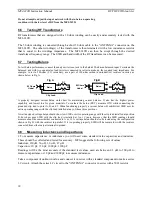
Testing Baluns
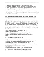
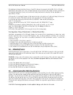
To test balun performance, connect the analyzer
Antenna
jack to the balun's 50-ohm unbalanced input. Terminate the
balanced side with two equal-value load resistors connected in series to make up the required load impedance. For
example, to test a 200-ohm (4:1) secondary, use a pair of 100-ohm carbon (non-inductive) resistors in series, as
shown below in Fig A:
Balun
>
A
C
B
Clip Lead
50 Ohms
Unbal
R1
R2
Balun
Clip Lead
50 Ohms
Unbal
R1
R2
<
A
C
Fig A
Fig B
A properly designed current balun works best for maintaining current balance. It also has the highest power
capability and lowest loss for given materials. To evaluate the balun (DUT), measure
SWR
while connecting the
grounded clip lead to point A, B, and C. When functioning properly, a current balun will exhibit low SWR over its
entire operating range with the clip lead installed at any of those three positions.
A well designed voltage balun should show low SWR over its operating range with the clip lead installed at position
B, but show poor SWR with the clip lead is installed at A or C (note, however, that the SWR readings should
measure about the same whether connected to A or C). A voltage balun should also be tested using the configuration
shown in Fig B, with the resistors in parallel. If it is operating properly, SWR will be remain low with the resistors
connected from either output terminal to ground.
6.8
Measuring Inductance and Capacitance
F
To measure capacitance or inductance you will need some standard value capacitors and inductors.
These should be collected and tested for accuracy. MFJ suggests the following sets of values:
Inductors: 330
µ
H, 56
µ
H, 5.6
µ
H, .47
µ
H
Capacitors: 10 pF, 150 pF, 1000 pF, 3300 pF
Readings will be the most accurate if the standard test values used are between 0.5
µ
H to 500
µ
H to
measure capacitance or 10 pF and 5000 pF to measure inductance.
Take a component of unknown value and connect it in series with a standard component to make a series
LC circuit. Attach the series LC circuit to the "ANTENNA" connector in series with a 50
Ω
resistor.
Содержание MFJ-249D
Страница 1: ......
Страница 16: ...MFJ 989C VersaTuner V Instruction Manual 14 ...


