Metso Jamesbury Скачать руководство пользователя страница 7


IMO 

2/19


IMO-R26 EN 

7

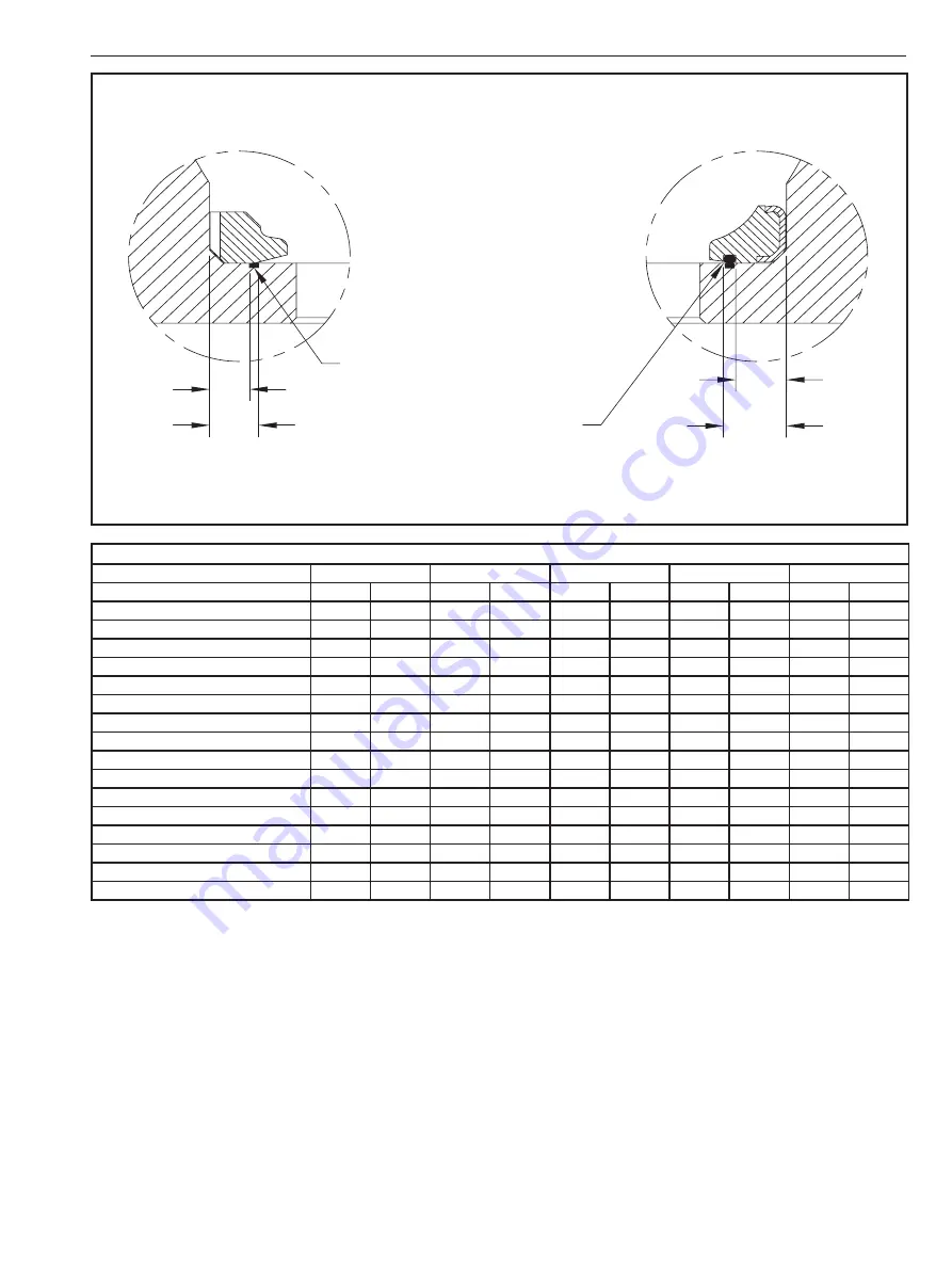
Figure 6:  Seat Sealing Critical Area

Seat Sealing Area

A

B

A

B

Seat Sealing Area

Xtreme® (-9J), PTFE (-50),

MTFE (-49)

Sulphur Valve Barrier Seat 

Material Code -47 

(9RETS, 9RELS, SUZRC, SUZRL, SUZRS)

Table 1: Dimensions for ball valve seat cavity sealing location

Jamesbury

Size

PTFE (-50)

Xtreme

 (-9J)

MTFE (-49)

W-Barrier (-47)

Railroad Ball Valves

Full

STD

Amin

Bmax

Amin

Bmax

Amin

Bmax

Amin

Bmax

6RFT

1

-

0.212

0.292

-

-

0.212

0.292

-

-

6RA3

2

-

0.180

0.260

-

-

0.180

0.260

-

-

9RFT/9FRT/9150RRR

2

-

0.181

0.259

0.176

0.264

-

-

-

-

9RFT/9FRT/9150RRR

3

-

0.274

0.356

0.274

0.356

-

-

-

-

6RIB3

4

-

0.411

0.493

-

-

0.411

0.493

-

-

9RET/9REL/9150RR

4

-

0.400

0.483

0.400

0.483

-

-

-

-

9RETS/9RELS (Sulphur Service)

4

-

-

-

-

-

-

-

0.461

0.651

5RRR/5RFF/5RFT

-

1

0.097

0.176

-

-

0.097

0.176

-

-

7RRT/7150RR

-

1

0.097

0.176

0.145

0.224

-

-

-

-

5RRU/5FRF/5ATR/5RRF/5RRT/5RNT

-

2

0.174

0.260

0.266

0.352

0.174

0.260

-

-

7RRT/7150RR

-

2

0.174

0.260

0.266

0.352

-

-

-

-

5RRF/5RRT

-

3

0.209

0.290

-

-

0.209

0.290

-

-

7RRT/7150RR

-

3

0.210

0.293

0.209

0.289

-

-

-

-

5REB3

-

4

0.249

0.330

-

-

-

-

-

-

5RET/AZFRS/AZFRC/AZFRL

-

4

0.361

0.443

-

-

0.361

0.443

-

-

SUZRS/SUZRC/SUZRL (Sulphur Service)

-

4

-

-

-

-

-

-

0.320

0.398

6.4.2  Remediating Damage

Body and Cap/Insert sealing areas may be dressed by hand 

with 600 grit (minimum) sandpaper or equivalent so long as 

it is applied concentric to the seal and not across the sealing 

area.

For seat sealing areas that cannot be restored by hand 

dressing, a one-time machining allowance of 0.010 inches 

is provided on the overall seat cavity. This allowance may be 

used on a single cavity or shared between the 2 seat cavities 

(i.e. remove 0.010 inches on a body seat cavity or 0.005 

inches on both the body and cap/insert set cavities).

When machining, care should be taken to keep the sealing 

area flat and parallel with respect to the valve body joint and 

provide a 125 RA maximum surface finish with a circular lay. 

Bodies and caps/inserts that have been machined should 

be stamped, “MCH” next to the valve tag to indicate that the 

one-time machining allowance is no longer available for 

repair of the valve.

The repair facility must use their own judgement and 

experience when evaluating damage severity in sealing 

areas. Metso recommends that all repairs be confirmed by 

gas testing for shell and seat leakage. Metso’s recommend 

gas test procedure is provided in 

Section 7

.

Содержание Jamesbury

Страница 1: ...IMO R26 EN 2 2019 Jamesbury Tank Car Ball Valve Inspection Procedure Installation Maintenance and Operating Instructions ...

Страница 2: ...bers are printed on the back cover See also www metso com products valves tank car valves for the latest documentation SAVE THESE INSTRUCTIONS Subject to change without notice All trademarks are property of their respective owners TABLE OF CONTENTS 1 SCOPE 3 2 WARNINGS 3 3 GENERAL 3 4 VALVE CLEANING 3 5 GENERAL VALVE INSPECTION 3 5 1 Sealing Area Criteria 3 6 DETAILED INSPECTION OFVALVE COMPONENTS...

Страница 3: ...ting shall be used when inspecting parts Inspection mirrors may be used to achieve necessary angle of view Sealing Surfaces are areas on the valve components which arecriticaltothevalvesealingperformance Sealingsurfaces are shown in Figures 2 through 5 Seat sealing critical areas are the portion of the sealing surface defined in Figure 6 No damage as defined in sealing area criteria 5 1 shall be a...

Страница 4: ...Material which has been raised up or deformed is not acceptable and considered damage Any other damage in the non working zone is acceptable 6 2 Stem Sealing and functional surfaces are shown in Figure 2 Visually inspect stem for galling No galling is allowed Visually inspect packing or stem seal area and thrust bearing area sealing surfaces No damage is allowed in these areas If stem has threads ...

Страница 5: ... If equipped with NPT threads visually inspect and gage threads for damage If insert threads into body visually inspect the threads for damage Dry fit insert into the body thread to check fit Visually inspect the sealing surface between the valve and tank car for damage Figure 3 Typical Insert Sealing and Functional Areas Figure 4 Typical Cap Sealing and Functional Areas See Figure 6 See Figure 6 ...

Страница 6: ... damage If the body has threaded fasteners gage the threads for damage Replace any fastener where the threads are damaged or have been heated stretched or corroded Figure 5 Typical Body Sealing and Functional Areas See Figure 6 LEGEND Seal Surface Solid Line Functional Surface 6 4 1 Seat to Body Sealing Area The seat seal against the body occurs at the transition of the angle on the back of the se...

Страница 7: ...hur Service 4 0 320 0 398 6 4 2 Remediating Damage Body and Cap Insert sealing areas may be dressed by hand with 600 grit minimum sandpaper or equivalent so long as it is applied concentric to the seal and not across the sealing area For seat sealing areas that cannot be restored by hand dressing a one time machining allowance of 0 010 inches is provided on the overall seat cavity This allowance m...

Страница 8: ...atches the tank car mounting interface on which the valve will be installed Outboard fixture is a flange or fixture that seals against the outboard valve interface Test fixtures hoses fittings etc shall be clean to prevent introducing debris during testing 7 1 2 Gaskets Metso recommends testing with same gasket that will be used to install the valve on the tank car Use of non standard gaskets or o...

Отзывы: