


12
5 FT 70 en
4.10.2 Changing the seat
Remove the valve from the pipeline and detach the
actuator as described in Section 4.4 and Section 4.5.
Turn the ball (3) into a position where it does not
move during the operation, e.g. 90 degrees clock-
wise from the closed position.
Remove the locking shoulders of the insert (2) and
unscrew the insert using a seat retainer tool.
Hold the seat with an Allen key (11 mm) and
unscrew the bushing (35) with a wrench (17 mm).
Push the seat out of the bushing (35). Remove the
graphite seals (64). Do not damage the sealing sur-
faces.
Turn the ball into a such position where the unbro-
ken side of the ball points to the threaded flow port.
Mount the graphite seals (64) on the seat (7). Push
the sealing package into the bushing (35).
Mark direction of offset (eccentricity) with e.g. felt tip
marker pen at the hexagonal edge of the seat. Note
the offset between the ball and flow port centre lines
from Fig. 19. Lubricate the seat threads with
Molykote 321R or a similar substance.
Screw the bushing (35) with the seat and seals care-
fully into the body. When the seat meets the ball sur-
face, turn the bushing back so that the eccentric seat
can be turned into the right position. Observe the
position using the mark made ealier. Hold the seat
with an Allen key and screw the bushing with a
wrench. Move the Allen key carefully back and forth
to find the position where the seat is most loosen.
When you find the right position hold the seat in that
position and tighten the bushing until its threads are
at the same level as the threads in the body.
Turn the stem to ensure that the ball and the seat are
correctly aligned. The movement should be smooth.
Install the back seal (63) into the insert (2).
Screw the insert (2) onto the threads of the bushing
(35). Tighten the insert with a seat retainer tool. The
torques are given in Table 4.
Lock the insert by hitting it with a nail punch to make
juts over two notches (of four available) on the body.
4.10.3 Dismantling the valve
Remove the valve from the pipeline and detach the
actuator as described in Section 4.4 and Section 4.5.
Turn the ball (3) into a position where it does not
move during the operation, e.g. 90 degrees clock-
wise from the closed position.
Remove the locking shoulders of the insert (2) and
unscrew the insert using a seat retainer tool.
Hold the seat with an Allen key (11 mm) and
unscrew the bushing (35) with a wrench (17 mm).
Push the seat out of the bushing (35). Remove the
graphite seals (64). Do not damage the sealing sur-
faces.
Unfasten the nuts (17) of the bonnet. Pull the bonnet
out and remove the bonnet seal (66) from under the
bonnet.
Pull the stem (5) out from the body (1).
If the stem is too tight to be pulled by hand, proceed
as follows: turn the nuts (18) about 2 cm on the studs
(14) while they remain in place. Put the gland fol-
lower (9) on the stem so that it rests on the nuts. Pull
the stem out by holding a suitable wrench in the
groove under the stem teeth and by turning the
gland follower higher by means of the nuts. Use a
suitable sleeve between the wrench and the gland.
Remove the ball (3) from the body through the flow
opening.
Detach the upper bearing (15) from the body by tap-
ping it through the stem bore, using a suitable bar.
Do not use the stem!
Turn a screw into the threaded hole on the bottom
of the lower bearing to remove the bearing (16).
Threads of the lower bearing hole:
DN 25: M8
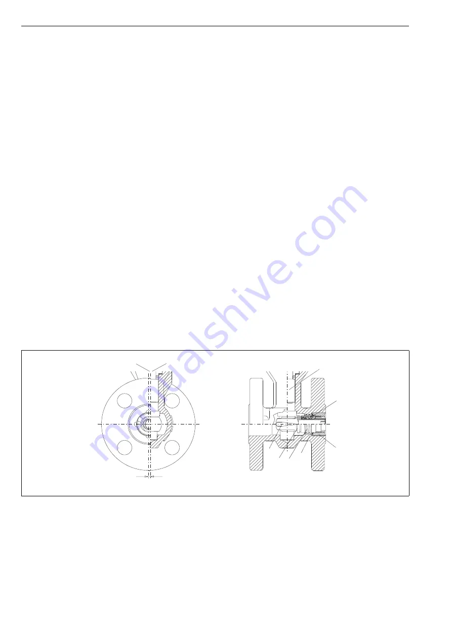
Fig. 19
Low capacity valve
Stem (5)
CL
Seat (7)
CL
offset
5
64
2
3
7
35
63


