


Page 22
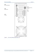
Technical data
Product Manual / Mounting Instructions
„Servo drives ARS 2320 FS, ARS 2340 FS and ARS 2360W FS“
Version 1.0
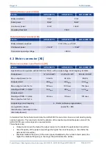
Listing of supported motor feedback systems
Type
Notes
Protocol
Analog incremental Encoder
ROD 400
ERO 1200/1300/1400
ERN 100/400/1100/1300
Heidenhain, encoder with zero- and reference pulse
Digital incremental Encoder
CDD50
Stegmann, encoder with hall sensors
Resolver
Standard
transmission ratio typ. 0,5 +- 10 %,
Input supply typ. 7 Vrms
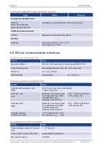
4.6 I/O and communication interfaces
Digital inputs and outputs [X1]
Feature
Value
Signal level DIN0-9
24V (8V...30V) active high, conforming with EN 61131-2
Logic outputs general
Galvanically separated, 24V (8V...30V) active high
DOUT0-3
24 V, max. 100 mA
DOUT4 [X6B]
Holding brake
24 V, max. 2 A
Analogue inputs and outputs [X1]
Feature
Value
High-resolution analogue input:
AIN0
10 V input range, 16 Bit, differentially,
< 250 µs delay time
Analogue input:
AIN1
Optionally, this input can also
be parameterized as digital
input DIN AIN1 with a
switching threshold at 8 V.
10 V, 10 Bit, single ended,
< 250 µs delay time
Analogue input:
AIN2
Optionally, this input can also
be parameterized as digital
input DIN AIN2 with a
switching threshold at 8 V.
10 V, 10 Bit, single ended,
< 250 µs delay time
Analogue outputs:
AOUT0 and AOUT1
10 V output range, 10 mA,
9 bit resolution, f
Limit
> 1 kHz
Incremental encoder input [X10]
Feature
Value
Parameterisable number of encoder
lines
1
– 2
28
lines/rev
Trace signals: A, #A, B, #B, N, #N
As per RS422 specification
Max. input frequency
1000 kHz


