background image


30 

Timing Diagrams  

Startup Condition Timing Diagram  

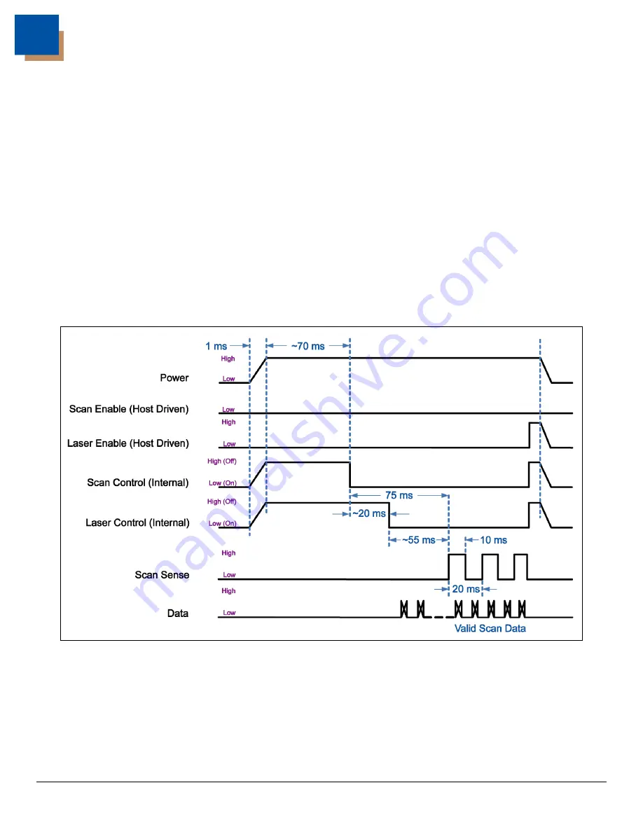
The timing diagram below illustrates the correct power up procedure for the IS4813 and IS4815 engines.   

Scan Enable and Laser Enable are host driven signals.  The Scan Enable and Laser Enable signals should be 
kept LOW (ON) at power up.  Scan Control and Laser Control are engine driven signals.   

The engine's onboard microcontroller drives the Scan Control and Laser Control signals so the engine's laser 
will not turn ON before the scan mirror starts moving.  This allows the onboard microcontroller to sense 
immediately any malfunction with the engine's scan mirror, turning OFF the laser automatically regardless of 
the state of Laser Enable signal being received from the Host. 

To ensure scan data integrity the Scan Sense pulses are delayed for approximately 55 ms after the Laser 
Enable signal goes LOW (ON).  To save power, turn OFF power to the engine after the scan is complete or 
when the engine is not scanning.  To turn the engine's power OFF, the Laser Enable signal from the host 
should be held HIGH (OFF) before turning OFF power to the engine. 


Figure 22. IS4813/IS4815 Timing Diagram, Startup Condition


Содержание IS4813

Страница 1: ...IS4813 IS4815 IS4823 and IS4825 Single Line Laser Scan Engine Integration Guide ...

Страница 2: ...ce or use of this manual This document contains propriety information that is protected by copyright All rights reserved No part of this document may be photocopied reproduced or translated into another language without the prior written consent of Metrologic 2009 Metrologic Instruments Inc All rights reserved Web Address www metrologic com Trademarks Metrologic and MetroSelect are trademarks or r...

Страница 3: ...nd 2 Dimensions 7 IS4823 and IS4825 0 Decode Printed Circuit Board Dimensions 8 Exit Beam Specifications 9 Enclosure Specifications Electrostatic Discharge ESD Cautions 10 Grounding 10 Power Supply 10 Power Sequencing 10 Host Flex Cable 11 Thermal Considerations 11 Printed Circuit Board Component Clearance 11 Magnetic Sensitivity 11 Airborne Contaminants and Foreign Materials 11 Beam Clearance 12 ...

Страница 4: ...ent Draw 25 C 24 Scan Engine Terminations IS4813 Pinout Connections 25 IS4815 Pinout Connections 25 Decode Printed Circuit Board Terminations USB Decode PCB 3 3V 26 USB Decode PCB 5V 27 TTL RS232 3 3V 5V 28 Flex Cable Specifications and Installation Guidelines 29 Timing Diagrams Startup Condition Timing Diagram 30 Scan Sense Timing Diagram 31 Bar Code Element Time Calculation 32 Regulatory Complia...

Страница 5: ...823 Support for 5VDC input voltage IS4815 IS4825 A 650 nm bright laser diode A narrow exit angle to provide precise beam positioning Automatic hardware scan sense A rugged die cast engine chassis with threaded mounting holes An optional mounting bracket for integration flexibility IS4823 IS4825 A 10 pin IS4813 IS4815 or 12 pin IS4823 IS4825 ZIF connector with industry standard pinout for seamless ...

Страница 6: ...on IS4823 3 3VDC Scan Engine with Decode PCB IS4825 5VDC Scan Engine with Decode PCB Model and Kit Delineation Figure 1 IS4823 IS4825 Model and Kit Delineation Accessories Part Number Description 19 00329 Flex Cable 12 POS 80 mm Length 19 07335 Flex Cable 10 POS 67 5 mm Length Labels Figure 2 Serial Number Label Enlarged For Illustration Purposes Option is not available for sale in all regions Con...

Страница 7: ... ZIF Connector 10 Pin 6 Printed Circuit Board and Shield 7 Die Cast Chassis Figure 3 IS4813 IS4815 IS4823 and IS4825 0 Decode Engine Assembly Item Description Item Location 1 Decode Printed Circuit Board 2 ZIF Connector 12 PIN 3 Flex Cable 12 POS 4 Pin Locator Holes see page 6 5 IS4813 or IS4815 Laser Scan Engine 6 Exit Beam Location Laser Light Aperture AVOID EXPOSURE LASER LIGHT IS EMITTED FROM ...

Страница 8: ... Laser Scan Engine 6 ZIF Connector 12 PIN 7 Decode Printed Circuit Board 8 0 10 Dia Clearance Holes for Mounting 2 Pls 9 M2 x 0 4 Threaded Bosses for Mounting 3 Pls 10 Bracket 11 Screw M1 2 6 36 mm T3 Thread Forming 12 Screw M1 6 x 35 5 mm Philips Stainless Steel with Patch 2 Pls Figure 5 IS4823 1 IS4825 1 Assembled Figure 6 IS4823 2 IS4825 2 Unassembled Option is not available for sale in all reg...

Страница 9: ...e 1 2 Screw M1 6 x 35 5 mm Philips Stainless Steel with Patch 2 3 IS4813 or IS4815 Scan Engine 1 4 Flex Cable 10 POS 1 5 Decode Printed Circuit Board 1 6 Flex Cable 12 POS 1 7 Bracket PCB Locking Bar 1 8 Screw M1 2 6 mm T3 Thread Forming 2 Tools Required Size Torx Screw Driver T3 Phillips Screw Driver 00 ...

Страница 10: ...faces For a non metallic mounting surface Use non magnetic M1 6 x 35 stainless steel screws Do not exceed 1 35 09 cm kg 1 17 08 in lbs of torque during screw installation Use a minimum mount thickness of 3 mm Use safe ESD practices when handling and mounting the engine For a metallic mounting surface The die cast engine chassis is at Vcc Use an insulator between the engine chassis and the host 005...

Страница 11: ...o when mounting the IS4800 series laser scan engine When securing the engine by utilizing the three M2 threaded inserts Use M2 x 0 4 Phillips Pan Head Type AB Steel Zinc Clear or equivalent screws Do not exceed 2 88 cm kg 2 5 in lb of torque when securing the engine assembly to the host Use a minimum mount thickness of 3 mm Use safe ESD practices when handling and mounting the engine assembly Figu...

Страница 12: ... the IS4800 series laser scan engine When securing the decode board 3M 4032 1 32 double coated urethane foam tape or equivalent Use safe ESD practices when handling and mounting the decode board Figure 10 IS4823 IS4825 Decode PCB Dimensions Specifications are for reference only and are subject to change without notice 3M is a trademark of 3M and or its subsidiaries worldwide ...

Страница 13: ...ications Figure 11 IS4800 Series Exit Beam Specifications See page see pages 12 15 for information on window material specifications and enclosure design considerations Specifications are subject to change without notice ...

Страница 14: ...be installed in a grounded host The die cast engine chassis is at Vcc Use an insulator between the engine chassis and host Use non metallic nylon or equivalent screws Power Supply The IS4813 IS4815 non decode engines are powered from the host device through the 3 3V or 5V and GND pins of the engine s 10 Pin ZIF connector IS4823 IS4825 decode engine assemblies are powered from the host device throu...

Страница 15: ...mperatures 0 C to 40 C for all operating modes Make sure ambient temperatures do not exceed this range in order to guarantee operation Operating the IS4800 in continuous mode for an extended period may produce considerable heating This mode should be limited and sufficient airflow should be provided whenever possible to minimize internal heating Excessive heating may potentially damage the IS4800 ...

Страница 16: ...ngence refers to multiple indices of refraction within one material This condition will induce polarization effects that can be detrimental to scan performance of the engine Check with a representative before utilizing a transparent polycarbonate material for the output window The exit window material should have a spectral transmission of at least 85 from 640 nm to 690 nm and should block shorter...

Страница 17: ...ecessing the window into the housing can also provided added protection against surface damage such as scratches and chips If an anti reflective coating is used there is no need to apply a polysiloxane coating Output Window Angle Note An improperly placed window has the serious potential to reduce the scan engine s performance Careful consideration must be made when designing the output window s d...

Страница 18: ...rance Exit Beam Elevation Angle α Minimum Projected Distance mm from the Engine s Base to the Window s Internal Surface L Minimum Window Angle θ 2 5 5 0 28 0 2 5 10 0 14 5 2 5 15 0 10 5 2 5 20 0 8 0 2 5 25 0 7 0 2 5 30 0 6 5 2 5 35 0 6 0 2 5 40 0 5 5 2 5 45 0 5 0 2 5 50 0 5 0 Figure 12 Specifications are subject to change without notice ...

Страница 19: ...ance Exit Beam Depression Angle β Minimum Projected Distance mm from the Engine s Base to the Window s Internal Surface M Minimum Window Angle θ 2 5 5 0 23 5 2 5 10 0 16 5 2 5 15 0 12 5 2 5 20 0 10 5 2 5 25 0 9 0 2 5 30 0 8 0 2 5 35 0 7 5 2 5 40 0 7 0 2 5 45 0 6 5 2 5 50 0 6 0 Figure 13 Specifications are subject to change without notice ...

Страница 20: ...om Engine Face Total 13 mm 5 2 mil 70 mm 2 75 95 mm 3 75 25 mm 1 00 19 mm 7 5 mil 57 mm 2 25 171 mm 6 75 114 mm 4 50 26 mm 10 4 mil 50 mm 2 00 210 mm 8 25 160 mm 6 25 33 mm 13 0 mil 50 mm 2 00 254 mm 10 00 204 mm 8 00 1D 49 mm 19 5 mil 75 mm 2 95 300 mm 11 81 225 mm 8 86 For non decode IS4813 and IS4815 engines depth of field data is for reference only Actual values may vary depending on environme...

Страница 21: ... timeout selected or when a bar code is scanned and transmitted Activate Deactivate Scanning Using D E A received E character initiates the scanning cycle The scanning cycle is terminated based on the default period of time 2 seconds variable laser timeout selected or receipt of a D or when a bar code is scanned and transmitted Activate Scanning with Address A configurable address character is use...

Страница 22: ...vation mode is monitored during the inactive laser cycles An SI is transmitted when the I O is active and an SO when it is inactive Once the scanning activation cycle is started the external I O monitoring status is maintained until the scanning cycle is terminated regardless of the actual I O level Continuous Blinky Mode The scanner will continuously blink on and off turning the scanning cycle on...

Страница 23: ...There is a 20 second window between commands If a 60 second timeout occurs the engine will send a nak Enter Serial Configuration Mode To enter serial configuration mode send the following command stx 999999 etx The engine will not scan bar codes while in serial configuration mode Note Serial configuration mode uses the current Baud Rate Parity Stop Bits and Data Bits settings that are configured i...

Страница 24: ...9999 etx 02h 39h 39h 39h 39h 39h 39h 03h ack or 06h Load Defaults stx 999998 etx 02h 39h 39h 39h 39h 39h 38h 03h ack or 06h Disable Code 128 stx 100103 etx 02h 31h 30h 30h 31h 30h 33h 03h ack or 06h Configure Prefix 1 stx 903500 etx 02h 39h 30h 33h 35h 30h 30h 03h ack or 06h Code Byte 0 stx 0 etx 02h 30h 03h ack or 06h Code Byte 7 stx 7 etx 02h 37h 03h ack or 06h Code Byte 1 stx 1 etx 02h 31h 03h ...

Страница 25: ...face IS4823 and IS4825 USB TTL RS232 Print Contrast 35 Minimum Reflectance Difference IS4813 and IS4815 Decode Dependent Number of Characters Read IS4823 and IS4825 Up to 80 data characters Maximum Roll Pitch Yaw 42 68 52 Mechanical Dimensions See pages 6 8 for detailed specifications IS4813 IS4815 Non Decode Engine 8 g 0 282 oz IS4823 IS4825 Bracketed 1 Assembly 15 g 0 529 oz Weight Maximum IS482...

Страница 26: ... mA 135 mA Idle Current 75 mA 50 mA 72 mA 45 mA Sleep Current 65 mA 5 5 mA 53 mA 15 mA Suspend Current USB 5 5 mA N A 0 30 mA N A Power Down Current TTL 5 5 mA 15 mA See pages 33 36 for regulatory compliance information Environmental Operating Temperature 0 C to 40 C 32 F to 104 F Storage Temperature 40 C to 70 C 40 F to 158 F Humidity 5 to 95 relative humidity non condensing Vibration Protection ...

Страница 27: ...Voltages Signal Signal Description Minimum Maximum Condition VIN Operating Voltage 3 0V 3 6V VIH 1 Input High RX CTS 2 5V VIL 1 Input Low RX CTS 0 8V VIH 2 Input High TTL_INV nWake 0 8 x Vin VIL 2 Input Low TTL_INV nWake 0 8V VIH 3 Input High EXT Trigger 0 8 x Vin VIL 3 Input Low EXT Trigger 0 8V VOH 1 Output High Voltage TX RTS 0 8 x Vin Isource 16 mA VOL 1 Output Low Voltage TX RTS 0 14 x Vin Is...

Страница 28: ...r down 3 6V or 5 5V VOL 3 Output Low Voltage Power down 0 2V Isink 8 mA PWRDWN nGoodRead and nBeeper are open drain outputs w 100K pull ups to VIN Actual VOH will be determined by the parallel resistance of the 100K pull up and any external impedance Current Draw 25 C USB TTL Signal Signal Description VIN 3 3V VIN 5V VIN 3 3V VIN 5V Continuous Scan mode Average current draw during continuous scan ...

Страница 29: ... at the start of the scan line 8 and 9 Ground Power Ground Figure 16 IS4813 10 No Connect No Connect IS4815 Engine Connections 10 Pin ZIF Connector Pin Signal Name Function 1 No Connect No Connect 2 Power VCC 5 0V 5 3 No Connect No Connect High Laser OFF 4 Laser Enable Low Laser ON only if pin 5 scan enable is also Low High Engine OFF 5 Scan Enable Low Engine ON High Bar 6 Digitized Bar Pattern Da...

Страница 30: ...n See Detailed Electrical Specifications starting on page 23 11 nEXT Wake Input Active Low Wakes Engine From Suspend or Sleep Mode 12 EXT Trig Input Active Low Signal Used as Trigger Input to Activate the Engine 10 Pin ZIF Connector Pin Signal Name Function 1 SDA I2 C Data Bi Directional Devices Function as Auxiliary Devices 2 GND Ground Power and Signal Ground 3 GND Ground Power and Signal Ground...

Страница 31: ...l Specifications starting on page 23 11 nEXT Wake Input Active Low Wakes Engine from Power Down or Sleep Mode 12 EXT Trig Input Active Low Signal Used as Trigger Input to Activate the Engine 10 Pin ZIF Connector Pin Signal Name Function 1 SDA I2 C Data Bi Directional Devices Function as Auxiliary Devices 2 GND Ground Power and Signal Ground 3 GND Ground Power and Signal Ground 4 Scan Sense Level c...

Страница 32: ...ing Current Good Scan See Detailed Electrical Specifications starting on page 23 11 nEXT WAKE Input Active Low Signal Used to Bring Engine Out of Power Down 12 EXT Trig Input Active Low Signal Used as Trigger Input to Activate the Engine 10 Pin ZIF Connector Pin Signal Name Function 1 SDA I2 C Data Bi Directional Devices Function as Auxiliary Devices 2 GND Ground Power and Signal Ground 3 GND Grou...

Страница 33: ...29 Flex Cable Specifications and Installation Guidelines Figure 21 Flex Cable Specifications and Installation Guidelines Specifications are subject to change without notice ...

Страница 34: ... the scan mirror starts moving This allows the onboard microcontroller to sense immediately any malfunction with the engine s scan mirror turning OFF the laser automatically regardless of the state of Laser Enable signal being received from the Host To ensure scan data integrity the Scan Sense pulses are delayed for approximately 55 ms after the Laser Enable signal goes LOW ON To save power turn O...

Страница 35: ... signals simultaneously without worrying about laser safety The Laser Enable signal can even be set LOW ON before the Scan Enable signal goes LOW ON If the scan mirror is moving and Laser Enable signal goes LOW ON the onboard microcontroller immediately turns ON the laser If Laser Enable signal is LOW ON and Scan Enable signal is HIGH OFF then the onboard microcontroller waits for the Scan Enable ...

Страница 36: ...ardware to resolve a varying range of minimum element times The minimum element time calculation for a given bar code size at a given distance is shown in Equation 1 below Minimum Element Time Element Size Spot Speed Equation 1 Example Bar code Size 5 2 mil Spot Speed 95 mm from face 650 inches second Minimum Element Time 0 0052 inches 650 inches second 8 0 µsec ...

Страница 37: ...o comply with all federal laser safety regulations The specifications required for agency approval are not obtainable until the IS4800 engine is used in its final configuration Metrologic is unable to fulfill these requirements because the scan engine will operate differently depending upon where it is used as a component The following information concerning the scan engine appears on the shipping...

Страница 38: ...ning lasers The manufacturer should consult the applicable government regulations for more information Copies of Product Reporting Guides other guides and related documents are available as PDF documents from the CDRH website at www fda gov cdrh comp eprc html Additional resources include the Division of Small Manufacturers International and Consumer Assistance DSMICA in Rockville Maryland at 1 80...

Страница 39: ...tives and standards dependent upon the type of product Information may be found at http europa eu int comm enterprise newapproach Laser Safety IEC 60825 1 1993 A1 1997 A2 2001 EN 60825 1 1994 A2 2001 A1 2002 Safety of Laser products Compliance with either of the standards listed above is required for the product to bear the CE mark Note Non EEA countries may impose additional testing certification...

Страница 40: ...r ou le laser Ne regardez jamais directement le rayon laser même si vous croyez que le scanner est inactif N ouvrez jamais le scanner pour regarder dans l appareil Ce faisant vous vous exposez à une rayonnement laser qú êst hazardous L emploi d appareils optiques avec cet équipement laser augmente le risque d endommagement de la vision Achtung Die Verwendung anderer als der hier beschriebenen Steu...

Страница 41: ...Product The warranty is void if the Product is not encased in a properly designed enclosure sealed to a prevent infiltration by airborne contaminants b protect against ESD humidity and mechanical shocks and c be non condensing or Product is opened by anyone other than Metrologic s repair department or authorized repair centers For additional information on enclosure design see pages 10 15 of the I...

Страница 42: ...38 Patents Worldwide patents pending ...

Страница 43: ... Electrical Current Draw 23 DC voltages 23 Max Ratings 23 safety 22 Electrostatic Discharge 10 EMC 33 36 EMI 11 Enclosure 10 F Field of View 16 Flex Cable 2 3 4 5 11 G Ground 10 25 I I O 17 Interface TTL RS232 2 8 21 USB 2 8 11 21 L Labels 2 Laser aperture 3 4 beam 10 class 22 enable 25 mode 17 power 21 safety 3 4 33 36 VLD 10 LED 17 Light Source 21 M Magnetic Sensitivity 10 11 Mode serial 19 Mode...

Страница 44: ...ration 19 Signals 23 T Tape 8 Temperature 11 22 Thermal Temperature 11 Timeout 17 Timing 31 Torque 6 8 Trigger 17 V Voltage 10 11 22 W Weight 21 Window angle 13 15 coatings 12 13 materials 12 specifications 12 15 transmission 12 Z ZIF 3 4 21 25 ...

Страница 45: ...ain Fax 91 80 4125 6719 866 460 8033 Customer Service Email info in metrologic com 888 633 3762 Technical Support Tel 34 913 272 400 Fax 856 537 6474 Fax 34 913 273 829 Email info us metrologic com Email info es metrologic com Japan Tel 81 3 3839 8511 United Kingdom Fax 81 3 3839 8519 South America Outside Brazil Email info jp metrologic com Tel 44 0 1256 365900 Tel 55 11 5182 7273 Fax 44 0 1256 3...

Страница 46: ...pean Repair Center Tel 800 436 3876 Customer Service Tel 86 512 67622550 Tel 34 913 751 249 866 460 8033 Customer Support Fax 86 512 67622560 Fax 34 913 270 437 888 633 3762 Technical Support Email info cn metrologic com Fax 856 228 6673 Sales Email info metrologic com ...

Страница 47: ......

Страница 48: ...Metrologic Instruments Inc 90 Coles Road Blackwood NJ 08012 00 02019 Rev G April 2009 ...

Отзывы: