METRObility Optical Systems R111-12 r Скачать руководство пользователя страница 11

Radiance 10Mbps Single Interface Line Cards       11

Link Loss Carry Forward (LLCF)

*

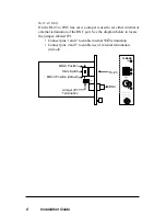
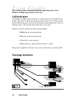
The Radiance 10Mbps single interface line cards incorporate an LLCF function
for troubleshooting a remote connection. When LLCF is enabled, the FL and TP
ports do not transmit a link signal until they receive a link signal from the
opposite port.

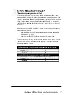
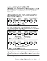
The diagram below shows a typical network configuration with a good link
status using Radiance line cards for remote connectivity. Note that LLCF is
enabled as indicated in the diagram.

Management

Station

Management

Station

Switch/Hub

w/SNMP

Switch/Hub

w/SNMP

Radiance

Line Card

Radiance

Line Card

LED lit = established link

LED unlit = no link

LLCF is ON

LLCF is ON

TP

TP

FL

Remote

Cable

If the connection breaks, the line card carries that link loss forward to the
switch/hub which generates a trap to the management station. The administrator
can then determine the source of the problem.

Link Loss Carried Forward

Link Loss Carried Forward

LED lit = established link

LED unlit = no link

Management

Station

Management

Station

Switch/Hub

w/SNMP

Switch/Hub

w/SNMP

Radiance

Line Card

Radiance

Line Card

LLCF is ON

LLCF is ON

TP

TP

Broken

FL Remote

Cable

Link Loss Carried Forward

LED lit = established link

LED unlit = no link

Management

Station

Management

Station

Switch/Hub

w/SNMP

Switch/Hub

w/SNMP

Radiance

Line Card

Radiance

Line Card

LLCF is ON

LLCF is ON

TP

Broken

TP

Cable

FL

Remote

Cable

Important: When connecting a Radiance line card with LLCF enabled to an auto-
negotiating device, force both sides of the configuration to 10Mbps and either full
or half duplex. This allows the card to immediately see link pulses and start passing
data.

* Line cards are shipped with LLCF disabled (OFF).

Содержание R111-12 r

Страница 1: ...11 16 R111 18 R111 1T RADIANCE 10MBPS SINGLE INTERFACE LINE CARDS PWR LK LK AT TP AT 10BASE PWR LK AT COL 10BASE LK AT FL M M PWR LK AT 10BASE FL LK AT M M PWR LK AT 10BASE LK AT FL S M PWR LK AT 10BA...

Страница 2: ...hemical optical or otherwise without prior explicit written permission of Metrobility Optical Systems Inc 2001 2002 2004 Metrobility Optical Systems Inc All rights reserved Printed in USA Radiance 10M...

Страница 3: ...pecifications 12 Product Safety EMC and Compliance Statements 14 Warranty and Servicing 15 Metrobility Metrobility Optical Systems NetBeacon and twister are registered trademarks of Metrobility Optica...

Страница 4: ...ut also increases network reliability The Radiance 10Mbps line card provides the following key features Fused power on each line card to protect the rest of the cards in the chassis from a short circu...

Страница 5: ...single interface line cards excluding the R111 12 incorporate LLCF Link Loss Carry Forward functionality as an aid in troubleshooting a remote connection The jumper configures the LLCF operation LLCF...

Страница 6: ...nation of the BNC port See the diagram below to locate the jumper labeled JP1 Connect pins 1 and 2 to enable internal 50 termination Connect pins 2 and 3 to enable use of external termination default...

Страница 7: ...MDI X switch observe the positioning of the following symbols the parallel symbol II indicates a straight through or parallel connection default the cross symbol X indicates a crossover connection Th...

Страница 8: ...FD RX LK T X TX 10 100 II x PWR 100 FD RX RX LK LK T X M M FL TX TX 10 100 II x II x PWR 100 FD 100 FD RX RX LK LK T X T X TX TX 10 100 RX LK TX FX M M II x PWR 100 FD RX LK T X TX 10 100 MGT 10 LK AT...

Страница 9: ...ports provide shielded RJ 45 connectors that support a maximum segment length of 100m Use Category 3 4 or 5 cables Fiber Optic Interface When making network connections make sure that the transmit TX...

Страница 10: ...agnosis and management There are separate activity AT and link LK indicators for each port When lit the LEDs indicate the following information PWR power normal operation LK link satisfactory link sta...

Страница 11: ...es that link loss forward to the switch hub which generates a trap to the management station The administrator can then determine the source of the problem Link Loss Carried Forward Link Loss Carried...

Страница 12: ..._______________________________ 350mV minimum Supported Link Length _________________________________________100m Cable Type ___________________________________ Category 3 4 or 5 UTP For NEBS Level II...

Страница 13: ...5 125 m Supported Link Length ___________________________ up to 2km full duplex Cable Type ________________________________50 125 or 62 5 125 m F O Multimode Fiber Optic Interface Long Haul Distance S...

Страница 14: ...to provide reasonable protection against harmful interference when the equip ment is operated in a commercial environment This equipment generates uses and can radiate radio frequency energy and if n...

Страница 15: ...umber and date of purchase To return a defective product for warranty coverage contact Metrobility Customer Service for a return materials authorization RMA number Send the defective product postage a...

Страница 16: ...e at http www metrobility com support manuals htm Product Registration To register your product go to http www metrobility com support registration asp 25 Manchester Street Merrimack NH 03054 USA tel...

Отзывы: