Metrix GX-1030 Скачать руководство пользователя страница 11

11

6. Mode Icon


  This mark indicates current mode is Phase-locked.


  This mark indicates current mode is Independent.

7. Menu

    Shows the menu corresponding to the displayed function. For example, Figure 4 shows the parameters of AM modulation.

8. Modulation Parameters Area

    Shows the parameters of the current modulation function. After selecting the corresponding menu, use number keys or knob to 

    change the parameter value.

4. FUNCTIONAL DESCRIPTION

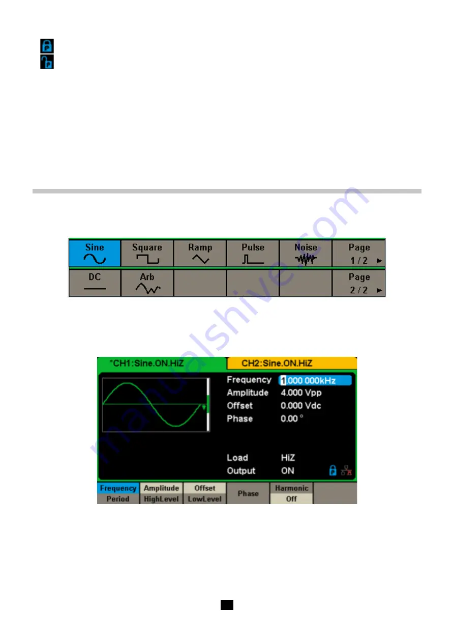
4.1.  TO SELECT THE WAVEFORM

Press 

[Waveforms]

 to enter the menu as Figure 5 shows. The example below will help familiarize with the waveform selection 

settings.

Figure 5 Waveform Selections

1.

 Press 

[Waveforms]

 key and then press 

[Sine]

 softkey. The 

GX 1030

 can generate sine waveforms with frequencies from 1 μHz to


    30  MHz.  By  setting  Frequency/Period,  Amplitude/High  level,  Offset/Low  level  and  Phase,  a  sine  waveform  with  different


    parameters can be generated

Figure 6: Sine Display Interface

2.

 Press

 [Waveforms]

 key and then press 

[Square]

 softkey. The generator can generate square waveforms with frequencies


    from 1 μHz to 30 MHz and variable duty cycle. By setting Frequency/Period, Amplitude/High level, Offset/Low level, Phase and


    DutyCycle, a square waveform with different parameters can be generated

Содержание GX-1030

Страница 1: ...EN User s manual Function Arbitrary Waveform Generator GX 1030...

Страница 2: ...ents taken at the source of low voltage installations Example power feeders meters and protection devices Measurement category III corresponds to measurements on building installations Example distrib...

Страница 3: ...To Set Sweep Function 42 5 11 To Set Burst Function 45 6 TO STORE AND RECALL 48 6 1 Storage System 49 6 2 File Type 49 6 3 File Operation 50 7 TO SET UTILITY FUNCTION 52 7 1 System settings 53 7 2 Tes...

Страница 4: ...ct the signal wire to a high voltage Do not touch the exposed contacts or components Use properly rated power line connections Use only the specified power line which has been approved by your local r...

Страница 5: ...extension cord are compatible with the voltage current range and that the circuit capacity is sufficient Once the checks are done connect the cable firmly The mains power cord included in the package...

Страница 6: ...USB Device USBTMC LAN VXI 11 LCD 4 3 display 480X272 points 2 2 OUTPUT CONNECTIONS The function generator output circuits operate as a voltage source with an impedance of 50 ohms At higher frequencie...

Страница 7: ...t signals Turn the device on and set it to the default settings To do this press Utility then System then Set To Default 1 Connect the BNC output of CH1 green to an oscilloscope 2 Press the Output key...

Страница 8: ...LE ADJUSTMENT To adjust the handle position of the GX 1030 please grip the handle by the sides and pull it outward Then rotate the handle to the desired position Figure 1 Viewing Position and Carrying...

Страница 9: ...Panel GX 1030 has a clear and simple front panel which includes a 4 3 inch screen menu softkeys numeric keyboard knob function keys arrow keys and channel control area Figure 2 Front Panel of GX 1030...

Страница 10: ...splays the load and output load as selected by the user Load Value of the output load as selected by the user Press Utility Output Load then use the softkeys number keys or knob to change the paramete...

Страница 11: ...shows The example below will help familiarize with the waveform selection settings Figure 5 Waveform Selections 1 Press Waveforms key and then press Sine softkey The GX 1030 can generate sine waveform...

Страница 12: ...metry a ramp waveform with different parameters can be generated Figure 8 Ramp Display Interface 4 Press Waveforms key and then press Pulse softkey The generator can generate pulse waveforms with freq...

Страница 13: ...he generator can generate a DC signal with a level up to 10 V into a HighZ load or 5 V into a 50 load Figure 11 DC Display Interface 7 Press Waveforms key and then press Page 1 2 lastly press the Arb...

Страница 14: ...B AM etc Pulse waveforms can only be modulated using PWM Noise and DC waveforms cannot be modulated Figure 14 Modulation Display Interface 2 Press Sweep the Sweep function will be enabled Sine square...

Страница 15: ...onds to switch between High Impedance and 50 load Figure 17 Output Keys 4 4 TO USE NUMERIC INPUT As shown in Figure 18 Front Panel Digital Input There are three sets of keys on the front panel which a...

Страница 16: ...s of basic waveforms directly 2 The Utility key is used to set the auxiliary system function such as output configurations interface setting system setting information performing the instrument self t...

Страница 17: ...ignal offset or low level The current parameter will be switched with a second press Phase Set the phase of the signal Menu Explanations of Sine Waveform To Set the Frequency Period Frequency is one o...

Страница 18: ...e parameter value directly and press the corresponding key to select the parameter unit Or use the arrow keys to select the digit to edit and then use the knob to change its value Figure 22 Setting th...

Страница 19: ...the set value of last power down 2 Input the desired phase Use the numeric keyboard to input the parameter value directly and press the corresponding key to select the parameter unit Or use the arrow...

Страница 20: ...vel Set the signal offset or low level The current parameter will be switched with a second press Phase Set the phase of the signal DutyCycle Set the duty cycle for square waveform Menu Explanations o...

Страница 21: ...y menu select Symmetry The symmetry parameter area is highlighted in the parameter display window and users can set the symmetry value here Figure 27 Ramp Parameters Display Interface Function menu Ex...

Страница 22: ...o change its value The generator will change the waveform immediately Figure 28 Setting Symmetry Note The methods of setting other parameters of ramp signal are similar to the sine waveform function 5...

Страница 23: ...gure below The pulse width setting range is limited by the Minimum Pulse Width and Pulse Period setting For detailed information please refer to specifications The default value is 200 s Pulse duty cy...

Страница 24: ...e desired rise edge Use the numeric keyboard to input the parameter value directly and press the corresponding key to select the parameter unit Or use the arrow keys to select the digit to edit and th...

Страница 25: ...press the corresponding key to select the parameter unit Or use the arrow keys to select the digit to edit and then use the knob to change its value Figure 33 Setting the Stdev To Set the Mean 1 Pres...

Страница 26: ...2 Arb The parameters include frequency period amplitude high level offset low level and phase Figure 36 Arb Parameters Display Interface DDS Function menu Explanations Frequency Period Set the signal...

Страница 27: ...oose Waveforms Page 2 2 Arb Arb Type Buit in to enter the following interface as shown in Figure 37 Figure 37 Built in Arbitrary Waveforms Press Common Math Engine Window Trigo or other menus to switc...

Страница 28: ...Airy function Besselj Bessel I function Bessely Bessel II function Dirichlet Dirichlet function Erf Error function Erfc Complementary error function ErfcInv Inverted complementary error function ErfIn...

Страница 29: ...signal Surge Surge signal Radar Analog radar signal Ripple Ripple wave of battery Gamma Gamma signal StepResp Step response signal BandLimited Bandwidth limited signal CPulse C Pulse CWPulse CW pulse...

Страница 30: ...cosine CosInt Integral cosine Coth Hyperbolic cotangent Csch Hyperbolic cosecant SecH Hyperbolic secant SinH Hyperbolic sine SinInt Integral sine TanH Hyperbolic tangent ACosH Arc hyperbolic cosine AS...

Страница 31: ...uareDuty30 Square waveform with 30 duty SquareDuty32 Square waveform with 32 duty SquareDuty34 Square waveform with 34 duty SquareDuty36 Square waveform with 36 duty SquareDuty38 Square waveform with...

Страница 32: ...Electromyogram Pulseilogram Pulseilogram ResSpeed Speed curve of the respiration ECG1 Electrocardiogram 1 ECG2 Electrocardiogram 2 ECG3 Electrocardiogram 3 ECG4 Electrocardiogram 4 ECG5 Electrocardio...

Страница 33: ...phase According to the Fourier transform a periodic time domain waveform is the superposition of a series of sine waveforms as shown in the equation below Generally the component with f1 frequency is...

Страница 34: ...e amplitude value and the select the desired unit from the pop up menu The units available are Vpp mVpp and dBc To select the Harmonic Phase After entering the harmonic setting menu press Harmonic Pha...

Страница 35: ...signal from an internal or external modulation source Press Mod AM Source to select Internal or External modulation source The default is Internal 1 Internal Source When internal AM modulation source...

Страница 36: ...level on the connector connected to the Aux In Out 6 V correspond to 100 depth When external modulation source is selected this menu is hidden To Set Modulation Frequency When internal modulation sou...

Страница 37: ...Out connector at the rear panel Freq Dev Set the frequency deviation Shape Sine Choose the modulating waveform Square Triangle UpRamp DnRamp Noise Arb FM Freq Set the modulating waveform frequency Fr...

Страница 38: ...e Aux In Out connector at the rear panel Phase Dev Phase deviation ranges from 0 360 Shape Sine Choose the modulating waveform Square Triangle UpRamp DnRamp Noise Arb PM Freq Set the modulating wavefo...

Страница 39: ...press Key Freq to set the rate at which the output frequency shifts between carrier frequency and hop frequency Use the numeric keyboard or arrow keys and knob to input the desired value The key freq...

Страница 40: ...tion only 1 mHz 50 kHz Table Menu Explanations of the ASK Parameters Note The methods for setting the parameters of ASK are similar to AM In addition the external modulating signal of ASK must be Squa...

Страница 41: ...with the CMOS level specification 5 9 8 PWM In PWM Pulse Width Modulation the pulse width of the pulse varies with the instantaneous voltage of the modulating waveform The carrier can only be pulse Pr...

Страница 42: ...ting Interface The width deviation cannot exceed the current pulse width The width deviation is limited by the minimum pulse width and current edge time setting 5 10 TO SET SWEEP FUNCTION In the sweep...

Страница 43: ...type Linear Set the sweep with linear profile Log Set the sweep with logarithmic profile Direction Up Sweep upward Down Sweep downward Page 2 2 Return to the previous page Table Menu Explanations of...

Страница 44: ...or manual The generator will generate a sweep output when a trigger signal is received and then wait for the next trigger source 1 Internal Trigger Choose Source Internal the generator outputs contin...

Страница 45: ...ator will output waveform with a specified number of cycles after receiving the trigger signal Waveforms that support N Cycle burst include sine square ramp pulse and arbitrary Press Burst NCycle Cycl...

Страница 46: ...pport infinite mode include sine square ramp pulse and arbitrary Press Burst NCycle Infinite and set the trigger source to external or manual The screen will display an infinite cycle burst as shown i...

Страница 47: ...utting the specified number of cycles Cycles Infinite Set the number of waveform cycle in an N Cycle 1 to 50 000 or Infinite If Infinite is chosen then a continuous waveform will be generated once a t...

Страница 48: ...Arbitrary waveform file Browse View the current directory Save Save the waveform to the specified path Recall Recall the waveform or setting information in the specific position of the memory Delete...

Страница 49: ...e the knob to shift between the directories to choose Local C or USB Device 0 Choose Browse press the knob to open the current directory Use the knob to switch between folder and files under the curre...

Страница 50: ...nt character Save Store the file with the current name Cancel Return to the Store Recall interface Table Menu Explanations of File Storage 4 Select the character Users can select the desired character...

Страница 51: ...ept the generator will delete the currently selected file To Copy and Paste File GX 1030 supports the internal and external storage to copy files from each other For example copy an arbitrary wave fil...

Страница 52: ...ounter setting Output Setup Set the output parameters of CH1 and CH2 CH Copy Coupling Set the track channel coupling or channel copy function Page 1 2 Go to the next page Table Menu Explanations of Ut...

Страница 53: ...e language Chinese PowerOn Default All the settings return to default when power on Last All the settings return to the setting of the last power on User All the settings recall in xml file Set to Def...

Страница 54: ...m Number Format to enter the following interface Figure 65 Set the Number Format Function Menu Settings Explanations Point Use dot to represent decimal point Use comma to represent decimal point Separ...

Страница 55: ...the setting will be applied when the instrument is powered on This setting is stored in non volatile memory and will not be influenced by the Set To Default operation Last includes all system paramet...

Страница 56: ...eep Time 1 s Trig Out Off Mode Linear Direction Burst Default Burst Period 10 ms Start Phase 0 Cycles 1 Cycle Trig Out Off Delay 521 ns Trigger Default Source Internal Table Factory Default Setting 5...

Страница 57: ...omatically 5 Press Utility Page 1 2 Firmware Update Or press Store Recall directly 6 Select the configuration file CFG and choose Recall to update the configuration file 7 After the updating is finish...

Страница 58: ...in help system There are 9 topics in the help list You can use the knob and or operation menus to select the help information that you want to read 7 2 TEST CAL Choose Utility Test Cal to enter the f...

Страница 59: ...cator lights test program BoardTest Run hardware circuit self test program Cancel Return to the Test Cal menu Table Menu Explanations of Self Test 1 ScrTest Select ScrTest to enter the screen test int...

Страница 60: ...isplay in blue color The top of the screen displays Please press 8 key three times to exit 3 LED Test Select LEDTest to enter the LED test interface the on screen white rectangle shapes represent the...

Страница 61: ...Explanations State Off Turn off the counter On Turn on the counter Frequency Measured frequency Period Measured period PWidth Measured positive width NWidth Measured negative width RefFreq Set the ref...

Страница 62: ...he pop up menu Or use the knob and arrow keys to change the parameter value 4 Coupling Mode Set the coupling model of the input signal to AC or DC The default is AC 5 HFR High Frequency Rejection can...

Страница 63: ...two channels and enable the generator to output with specified frequency and start phase For two signals whose frequencies are the same or a multiple thereof this operation will align their phases Wa...

Страница 64: ...tates of CH2 to CH1 Accept Perform the current selection and return to the Utility menu Return Give up the current selection and return to the Utility menu Table Menu Explanations of Channel Copy Note...

Страница 65: ...lCH1 AmplDev Ratio the amplitude ratio of CH1 and CH2 The resulting signal is represented by AmplCH2 AmplCH1 AmplRatio Phase Coupling 1 To Enable Phase Coupling Function Press PhaseCoup to turn phase...

Страница 66: ...the track function When the track function is enabled channel copy and coupling functions are disabled the user interface is switched to CH1 and cannot be switched to CH2 as shown in the following fi...

Страница 67: ...and programming please refer to Remote Control Manual 2 PC Software Users can use the PC software Measurement Automation Explorer of NI National Instruments Corporation to send commands to control th...

Страница 68: ...lick the Easy wave shortcut it will should below picture 2 Waiting for loading file and then proceed to the next step 3 Launch EasywaveX 4 Connection USB or LAN cable and select model 5 Select Wavefor...

Страница 69: ...tware and using USB or Ethernet connection follow operating instructions in pdf file SX GENE allows Transfers of arbitrary signals GX 1030 The recovery of a signal from a METRIX oscilloscope curve TRC...

Страница 70: ...when the generator is powered on the next time To Set Gateway The format of the gateway is nnn nnn nnn nnn and each nnn ranges from 0 to 255 It is recommended to acquire an available gateway from your...

Страница 71: ...Waveforms Basic Waveform and Arbitrary Waveform 1 When the frequency of the waveform is less than or equal to 10 MHz the sync signal is a Pulse with about 50 ns pulse width and the same frequency as t...

Страница 72: ...ization between two instruments Connect the 10 MHz In Out connector of generator A using internal clock to the 10 MHz In Out connector of generator B using external clock and set the output frequencie...

Страница 73: ...following figure 90 Figure 90 Overvoltage Protection Interface If the state is set to ON overvoltage protection of CH1 and CH2 will take effect once any of the following conditions is met When overvo...

Страница 74: ...30 minutes within specified operating temperature range 18 C 28 C 2 You must perform the Self Cal operation if the operating temperature changes by more than 5 All specifications are guaranteed excep...

Страница 75: ...ON Pulse width 32 6 ns min resolution 1 ns Rise Fall time 10 90 typical value 1 kHz 1 Vpp 16 8 ns to 22 4 s Overshoot 3 Jitter 300 ps cycle 0 05 ppm of period 9 2 5 ARBITRARY WAVEFORM SPECIFICATION Wa...

Страница 76: ...ise Arbitrary 1 mHz 20 kHz Frequency deviation 0 0 5 BW BW is the max output frequency limited by frequency setting 9 6 3 PM MODULATION Carrier Sine Square Ramp Arbitrary Source Internal External Modu...

Страница 77: ...l trigger Trigger delay 100 s Trigger source Manual External or Internal 9 9 REFERENCE CLOCK INPUT OUTPUT 9 9 1 REFERENCE CLOCK INPUT Frequency 10 MHz Input impedance 5 k AC coupling Amplitude 1 4 Vpp...

Страница 78: ...ntrinsic uncertainty plus the effects of variation of the quantities of influence supply voltage temperature interference etc as defined in standard IEC 61557 5 The uncertainties are expressed in of t...

Страница 79: ...ARNING To avoid any damage to the surface of the instrument do not use any abrasive or chemical cleaning agents Daily Maintenance Do not store or leave the instrument in places where the display scree...

Страница 80: ...warranty does not apply in the following cases Inappropriate use of the equipment or use with incompatible equipment Modifications made to the equipment without the explicit permission of the manufac...

Страница 81: ...4 85 Fax 33 1 46 27 73 89 info chauvin arnoux com www chauvin arnoux com INTERNATIONAL Chauvin Arnoux T l 33 1 44 85 44 38 Fax 33 1 46 27 95 69 Our international contacts www chauvin arnoux com contac...

Отзывы: