Electrical Installation Safety Trainer
AD 1 - MI 3399
43
1.4.5 Earth Resistance and Contact Voltage
The actual contact voltage is calculated from the measured earth resistance and trip-
out current. In order to get valid measurements the correct RCD settings have to be
selected.
Additional protection against too high contact voltage (
U
CL
– contact voltage limit) is
ensured, but only in case that earth resistance of the object is low enough.
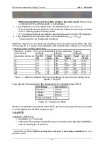
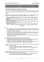
Nominal differential current
I
Δ
n
(mA)
10
30
100
300
500
1000
Max. allowed Earth Resistance
value at U
CL
= 50 V (Ω)
5000
1666
500
166
100
50
Max. allowed Earth Resistance
value at U
CL
= 25 V (Ω)
2500
833
250
83
50
25
Table 1-5: Maximum allowed earth resistance (Z
L-PE
) values for RCD protected
installations
Note:
In TT installation systems the earthing resistance R
E
represents the main part of
the loop impedance. Therefore the loop test can be suitable for measuring earthing
resistance of objects, systems etc.
If the RCD is installed downstream, the installation and parts of wiring are not
protected. In this case the limit for over current protection must be considered. A
typical example is a socket with integrated RCD.
If a RCD device is not present then the selected limit must be set according to the
used fuse characteristic.
Some Examples of evaluation of the Earth resistance value:
In case the RCD Nominal differential current is 500mA and Max. allowed contact
voltage is 50V, the Max. allowed Earth resistance value is
100 Ω
.
In case the RCD Nominal differential current is 30mA and Max. allowed contact
voltage is 25V, the Max. allowed Earth resistance value is
833 Ω
.
In case that the Earth resistance value is higher than the limit, the next possible
solutions are recommended:
-
Tracing of possible bad contacts in the tested mains socket.
-
Tracing of possible bad contacts in the PE conductor from the fuse box to
the mains socket.
-
Tracing of possible bad earthing of the object or no earthing at all.
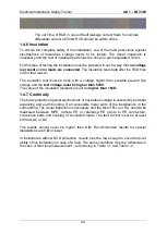
Where the Earth resistance of the object is within the allowed values, the additional
test of RCD is needed to ensure the safety protection:
-
Trip out Time of RCD in case of fault leakage current flows the same as
nominal differential current of RCD should be within 300ms.
Содержание MI 3399
Страница 27: ...Electrical Installation Safety Trainer AD 1 MI 3399 27...
Страница 28: ...Electrical Installation Safety Trainer AD 1 MI 3399 28 AD 1 MI 3399 EIS Electrical Installation Safety Trainer...
Страница 46: ...Electrical Installation Safety Trainer AD 1 MI 3399 46 3 Exit settings...
Страница 74: ...Electrical Installation Safety Trainer AD 1 MI 3399 74...
Страница 122: ...Power and Voltage Quality Trainer AD 2 MI 3399 122 AD 2 MI 3399 PQA Power and Voltage Quality Trainer...
Страница 197: ...Power and Voltage Quality Trainer AD 2 MI 3399 197 Figure 4 89 Transient Chart view...
Страница 204: ...PAT Appliances Machines Safety Trainer AD 3 MI 3399 204...
Страница 205: ...PAT Appliances Machines Safety Trainer AD 3 MI 3399 205 AD 3 MI 3399 PAT Appliances Machines Safety Trainer...
Страница 249: ...PV Photovoltaic Systems Trainer AD 4 MI 3399 249...
Страница 250: ...PV Photovoltaic Systems Trainer AD 4 MI 3399 250 AD 4 MI 3399 PV Photovoltaic Systems Trainer...

