background image

METRA.  THE WORLD’S BEST KITS.™

© COPYRIGHT 2004-2011  METRA ELECTRONICS CORPORATION


APPLICATIONS

1-800-221-0932

metraonline.com

Cutting Tool • Phillips Screwdriver • Socket Wrench 

TOOLS REQUIRED

Ford/Mazda multi-kit 

2008-Up

99-5814/99-5814S

B

A

• A)  Radio Housing  • B) ISO Brackets • C) Trim Plate  • D) Double DIN Brackets 
• E) Double DIN Trim Plate • F) Pocket • G) (2) Spare Radio Housing Panel Clips

KIT FEATURES

KIT COMPONENTS

• DIN Radio Provision with Pocket
• ISO Mount Radio Provision with Pocket
• Double DIN Radio Provision
• Stacked ISO Mount Units Provision

Painted to match factory dash: 
99-5814=Black, 99-5814S=Silver

WIRING & ANTENNA CONNECTIONS

 (Sold Separately)

                 Wiring Harness: 
                 • XSVI-5520-NAV Ford Interface 2006-up
                 • 70-5522-Ford Sub harness 2003-up


 Antenna Adapter: 

                  • 40-CR10 Chrysler/GM antenna adapter 2002-up
                  • AFSI-02 if equipped w/ sync

See application list inside

INSTALLATION INSTRUCTIONS FOR PART 99-5814

F

E

D

C

G

Содержание 99-5814

Страница 1: ...re Radio Housing Panel Clips KIT FEATURES KIT COMPONENTS DIN Radio Provision with Pocket ISO Mount Radio Provision with Pocket Double DIN Radio Provision Stacked ISO Mount Units Provision Painted to match factory dash 99 5814 Black 99 5814S Silver WIRING ANTENNA CONNECTIONS Sold Separately Wiring Harness XSVI 5520 NAV Ford Interface 2006 up 70 5522 Ford Sub harness 2003 up Antenna Adapter 40 CR10 ...

Страница 2: ...ginning any installation All accessories switches and especially air bag indicator lights must be plugged in before reconnecting the battery or cycling the ignition NOTE There are 2 extra radio housing panel clips included with the kit in case removal of the kit is necessary at any time NOTE Refer also to the instructions included with the aftermarket radio Ford Escape 2008 Up Mazda Tribute 2008 U...

Страница 3: ...move the 2 7 MM screws exposed at the top of the factory radio panel Figure B 3 Unclip the accessory socket switch aux input panel below the radio Unplug and remove the panel Figure C Continue on page 2 1 Dash Disassembly All Vehicles Figure A 99 5814 Figure B Figure C ...

Страница 4: ...ng the ground strap to the radio brackets Unplug and remove the radio 6 Remove 4 Torx screws securing the climate controls to the factory radio panel Remove the climate controls and retain them with the factory screws for use during kit assembly Figure E Continue to kit assembly Dash Disassembly All Vehicles Figure A REAR CLIMATE CONTROL REAR OF RADIO Figure B ...

Страница 5: ...dware removed in step 7 of dash disassembly Figure A Note There are 2 extra radio housing panel clips included with the kit in case removal of the kit is necessary at any time Figure B Continue to kit assembly Kit Preparation Figure A TWO EXTRA RADIO HOUSING RETAINING CLIPS Figure B ...

Страница 6: ...g tabs outward Figure A 2 Slide the aftermarket radio into the DIN cage and until it snaps into place Figure B 3 Snap the pocket into the radio housing Figure C Reassemble dash in reverse order of disassembly DIN Mount Radio Provision With Pocket Figure A Figure B Figure C 4 99 5814 ...

Страница 7: ...lide the radio into the radio housing until it snaps into place Figure B 3 Snap the trim plate onto the front of the Radio Housing Figure B 4 Snap the Pocket into the radio housing Figure C Reassemble dash in reverse order of disassembly ISO Mount Radio Provision With Pocket Figure A Figure B Figure C ...

Страница 8: ... B 3 Slide the Double DIN radio into the DDIN bracket radio housing assembly and secure the radio to the assembly using the screws supplied with the radio Figure C 3 Snap the Double DIN trim plate onto the front of the radio housing assembly Figure C Reassemble dash in reverse order of disassembly Double DIN Radio Provision Figure A Figure B Figure C ...

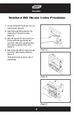
Страница 9: ...B 3 Slide the stacked ISO mount units into the bracket housing assembly and secure the units to the assembly using the screws supplied with the units Figure C 4 Snap the Double DIN trim plate onto the front of the radio housing assembly Figure C Reassemble dash in reverse order of disassembly Stacked ISO Mount Units Provision Figure A Figure B Figure C ...

Страница 10: ...METRA THE WORLD S BEST KITS COPYRIGHT 2004 2011 METRA ELECTRONICS CORPORATION 1 800 221 0932 metraonline com REV 10 05 11 INSTALLATION INSTRUCTIONS FOR PART 95 5817 ...

Отзывы: