background image

99-3303

6

K

I

T

A

S

S

E

M

B

L

Y

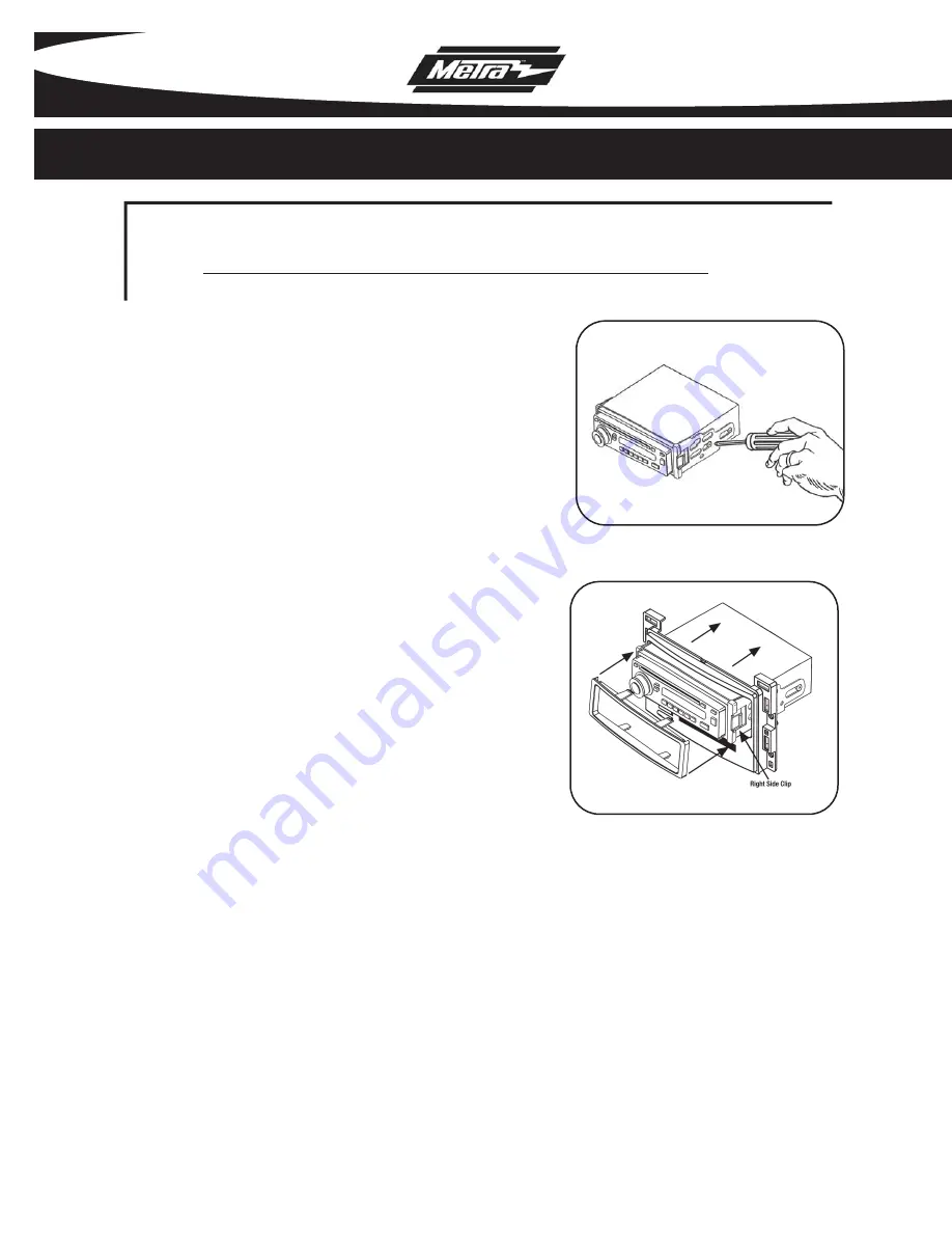
ISO DIN HEAD UNIT PROVISIONS:

Mount the ISO Brackets to the head unit with
the screws supplied with the unit.
(

Figure A)

1

A

Slide the head unit into the radio opening
until the side clips engage.

(Figure B)

2

Snap the Trim plate into the Radio Housing.

(Figure B)

3

B

Содержание 99-3303

Страница 1: ...olet Malibu 2004 2007 Chevrolet Malibu Classic 2008 Pontiac G6 2005 2009 DIN Head Unit Provision with Driver Information Center DIC ISO DIN Head Unit Provision with Driver Information Center DIC A Rad...

Страница 2: ...cket 5 ISO Head Unit Provision with Pocket 6 Final Assembly 7 Operation of the 99 3303 8 T ABLE OF CONTENTS KNOWLEDGE IS POWER Enhance your installation and fabrication skills by enrolling in the most...

Страница 3: ...rim pieces from both sides of steering wheel Figure A 1 2 Unclip and remove side panel from driver s side of dash with door open and remove 2 7MM screws Figure B 3 Remove 2 7MM screws from bottom edge...

Страница 4: ...ze sides together to open further and remove the remaining 4 7MM screws Unclip the black vent cover under the glove box then unclip and remove entire glove box assembly Figure F 7 Unclip and remove tr...

Страница 5: ...it 1 A Open glove box and remove 6 screws from outer edge then unclip and remove box Figure A 2 Remove 4 screws from panel below steer ing column and unclip and remove panel Figure B 3 Unclip and remo...

Страница 6: ...rim panel from above glove box Figure A 2 Unclip upper edge of panel below steering column and let hang Not necessary to remove completely Figure B 3 Unclip and remove small trim panel to right of ign...

Страница 7: ...cking tabs down Figure A 1 A Slide the aftermarket head unit into the cage and secure Figure B NOTE A snap in DIN spacer has been provided for some applications where depth is an issue Snap the spacer...

Страница 8: ...PROVISIONS Mount the ISO Brackets to the head unit with the screws supplied with the unit Figure A 1 A Slide the head unit into the radio opening until the side clips engage Figure B 2 Snap the Trim...

Страница 9: ...hite Amp Ground Black White Illumination Orange Dimmer Orange White Right Front Gray Right Front Gray Black Left Front White Left Front White Black Right Rear Violet Right Rear Violet Black Left Rear...

Страница 10: ...ble 1 0 Updating a function While in the Settings and Adjustment mode use the INFO and ENTER buttons to adjust the function selected and displayed on the LCD See Table 1 0 When OnStar activated INFO a...

Страница 11: ...9 NOTES 99 3303...

Страница 12: ...INST993303 1 800 221 0932 www metraonline com Rev 05 27 09 COPYRIGHT 2004 2009 METRA ELECTRONICS CORPORATION INST99 3303...

Отзывы: