Metos SF 500 Скачать руководство пользователя страница 21

13.2.2009

Rev. 4.0

Technical specifications

17

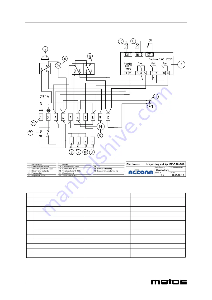
Wiring diagram SF; 500, 700; CCU

1

Solenoid valve

Magnetventil

Magneettiventtiili

2

Electronic control device

Elektronisk styrenhet

Elektroninen ohjausyksikkö

3

Defrost heat element 230V

Avfrostningselement 230V

Sulatusvastus 230V

4

Door switch

Dörrbrytare växlande

Ovikytkin

5

Fan for condenser

Förångarfläkt

Höyrystimen puhallin

6

Light 230V

Belysning 230V

Valaisin 230V

7

Switch

Brytare

Kytkin

8

Discharge heat element 230V

Avloppsvärme 230V

Lämpölanka (poistoputki) 230V

9

Gasket heat element 230V

Karmvärme 230V

Lämmitysvastus (ovitiiviste) 230V

10

Defrost water heat element 230V

Tövattenelement 230V

Vastus (haihdutus) 230V

11

Terminal block

Kopplingsplint

Liitinrima

12

Manual timer 4 h

Manuell timer 4 h

Manuaaliajastin 4 h

15

Probe for defrost

Sensor avfrostning

Anturi sulatukselle

16

Probe for thermostat

Sensor temperaturvisning

Anturi termostaatille

Содержание SF 500

Страница 1: ...BLAST FREEZER SF TYPE 500 700 Accessories CENTRAL REFRIGERATION ATTACHMENT Installation and Operation Manual S N 56454 Rev 4 0 4155069 4155076 4135577 4135584...

Страница 2: ......

Страница 3: ...General 4 4 1 1 Freezing 4 4 2 Operation 4 4 2 1 Freezing 4 4 2 2 Observe during operation 5 4 3 After use 5 4 3 1 Cleaning 5 4 3 2 Service by the user 6 4 3 3 Service by authorised service personnel...

Страница 4: ...13 2 2009 Rev...

Страница 5: ...ized by the manufacturer and using original spare parts Not complying with the above may put the safety of the appliance in danger 1 1 Symbols used in the manual This symbol informs about a situation...

Страница 6: ...en the cold cabinet is not used for a long time it should be unplugged from the power supply and the interior should be cleaned and dried carefully Doors may be dangerous e g for playing children so s...

Страница 7: ...ll only be used for freezing foods and beverages The manufacturer is not responsible for the consequences if the appliance is used for other purposes 3 2 Construction The front panel of the cabinet ha...

Страница 8: ...trying various combinations you will find a suitable freezing time for each situtation The capacities below are indicative values assuming that the product thickness is max 50 mm By reducing the amoun...

Страница 9: ...the defrost operation If possible wait before starting the cabinet until the defrost cycle has terminated the display shows temperature In case you use the cabinet for contemporary storage of products...

Страница 10: ...from the power supply Use either a vacuum cleaner or a soft brush When brushing the condenser be careful not to damage the aluminium grid 4 3 3 Service by authorised service personnel All other maint...

Страница 11: ...fore switching it on This makes sure that the compressor oil sets into place The cabinet should always be stored indoors If the cabinet has been stored in a place where the temperature of the cooling...

Страница 12: ...hours in place it can be started Connect the appliance to the power supply with an earthed socket For making the connection a socket protected with a 16 A fuse has to be provided Check that the local...

Страница 13: ...button 2 To increase the value press the upper button 1 To decrease the value press the lower button 3 The value will be saved automatically Within approx 15 seconds the display will show the interna...

Страница 14: ...h on the display Press the upper button 1 to display the alarm codes Alarm code Action A1 High temperature alarm A2 Low temperature alarm A4 Door alarm A15 Alarm signal DI input A45 Standby mode r12 o...

Страница 15: ...appropriate air circulation Check the cabinet surroundings Ambient temperature is too high Make sure that the appliance has not been placed near a heat source Move the cabi net to a cooler place and...

Страница 16: ...13 2 2009 Rev 4 0 Troubleshooting11 12...

Страница 17: ...4 0 Technical specifications 13 8 Technical specifications Refrigeration circuit diagram Wiring diagram SF 500 Wiring diagram SF 700 Wiring diagram SF 500 700 CCU Installation drawing 500 Installatio...

Страница 18: ...Refrigeration circuit diagram...

Страница 19: ...rystimen puhallin 6 Light 230V Belysning 230V Valaisin 230V 7 Switch Brytare Kytkin 8 Discharge heat element 230V Avloppsv rme 230V L mp lanka poistoputki 230V 9 Gasket heat element 230V Karmv rme 230...

Страница 20: ...sning 230V Valaisin 230V 7 Switch Brytare Kytkin 8 Discharge heat element 230V Avloppsv rme 230V L mp lanka poistoputki 230V 9 Gasket heat element 230V Karmv rme 230V L mmitysvastus ovitiiviste 230V 1...

Страница 21: ...t H yrystimen puhallin 6 Light 230V Belysning 230V Valaisin 230V 7 Switch Brytare Kytkin 8 Discharge heat element 230V Avloppsv rme 230V L mp lanka poistoputki 230V 9 Gasket heat element 230V Karmv rm...

Страница 22: ...13 2 2009 Rev 4 0 Technical specifications 18 Installation drawing 500 J G...

Страница 23: ...13 2 2009 Rev 4 0 Technical specifications 19 Installation drawing 700 G J...

Страница 24: ...d plug 3 m cable Weight 500 130 kg Weight 700 190 kg Capacity 500 473 litres Capacity 700 705 litres Shelves dimensions 500 454x530 mm Shelves dimensions 700 655x530 mm Width W 500 600 mm Width W 700...

Страница 25: ......

Отзывы: