METER TEROS 10 Скачать руководство пользователя страница 16

12

SySTEM

COMpLIANCE

Manufactured under ISO 9001:2015

EM ISO/IEC 17050:2010 (CE Mark)

2014/30/EU and 2011/65/EU

EN61326-1:2013 and EN55022/CISPR 22
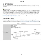
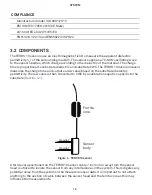
3.2  COMpONENTS

The TEROS 10 sensors use an electromagnetic field to measure the apparent dielectric 
permittivity (

e

a

) of the surrounding medium. The sensor supplies a 70-MHz oscillating wave 

to the sensor needles, which charge according to the dielectric of the material. The charge 
time is proportional to substrate dielectric and substrate VWC. The TEROS 10 microprocessor 
measures the charge time and outputs a raw value based on the substrate dielectric 
permittivity. The raw value is then converted to VWC by a calibration equation specific to the 
substrate (

Section 4.1

).

Needle 1

Needle 2

Sensor
body

Ferrite
core

Figure 4  TEROS 10 sensor

A ferrite core positioned on the TEROS 10 sensor cable 7.6 cm (3 in) away from the sensor 
head is utilized to isolate the sensor from any interferences in the system. This mitigates any 
potential noise from the system on the measured sensor data. It is important to not attach 
anything to the section of cable between the sensor head and the ferrite core as this may 
influence the measurements.

Содержание TEROS 10

Страница 1: ...TEROS 10...

Страница 2: ......

Страница 3: ...R Logger 8 2 3 Interfacing With Data Loggers 9 3 System 10 3 1 Specifications 10 3 2 Components 12 3 3 Theory 13 4 Service 14 4 1 Calibrations 14 4 1 1 Mineral Soils 14 4 1 2 Soilless Media 14 4 1 3 A...

Страница 4: ...ii...

Страница 5: ...rous materials This manual guides the customer through the sensor features and applicationsand describes how to use the sensor successfully Volumetric water content VWC measurement Soil substrate wate...

Страница 6: ...uctions and have the proper protections in place to safeguard sensors from damage If installing sensors in a lightning prone area with a grounded data logger see the application note Lightning surge a...

Страница 7: ...cm Installing Create Hole Avoid interfering objects Large metal objects can affect the sensor function and distort readings Roots or rocks that could potentially bend the needles and should be avoide...

Страница 8: ...urement Installing the sensor with the body oriented horizontally on its side will provide measurements at a more discreet depth See Measurement volume of METER volumetric water content sensors for mo...

Страница 9: ...ogger mast to ensure cable weight does not cause sensor to unplug conduit zip tie mast ERROR OK TEST P1 P2 P3 P4 P5 P6 Securing excess cable Backfill the Hole Return soil to the hole packing the soil...

Страница 10: ...ce at measurement site Disadvantage Requires a specialized installation tool that can be rented from METER Trench This method is best for shallow installations less than 40 cm This requires digging a...

Страница 11: ...is 40 m 2 2 1 CONNECT TO METER DATA LOGGER The TEROS 10 sensor works seamlessly with METER ZENTRA EM60 or Em50 data loggers Check the METER Download web page for the most recent data logger firmware L...

Страница 12: ...g Connect the TEROS 10 wires to the data logger as illustrated in Figure 2 with the supply wire brown connected to the excitation the analog out wire orange to an analog input and the bare ground wire...

Страница 13: ...e sensor does not become disconnected during use 2 3 INTERFACING WITH DATA LOGGERS The TEROS 10 sensor is designed to work most efficiently with METER data loggers All METER readout devices use a 3 0...

Страница 14: ...or most substrates Resolution 0 001 m3 m3 Accuracy Mineral soil calibration 0 03 m3 m3 typical in mineral soils that have solution EC 8 dS m Soilless media calibration 0 05 m3 m3 typical in media that...

Страница 15: ...d cable length is needed Connector Types 3 5 mm stereo plug connector or stripped and tinned wires ELECTRICAL AND TIMING CHARACTERISTICS Supply Voltage VIN to GND Minimum 3 0 VDC Typical NA Maximum 15...

Страница 16: ...The TEROS 10 microprocessor measures the charge time and outputs a raw value based on the substrate dielectric permittivity The raw value is then converted to VWC by a calibration equation specific t...

Страница 17: ...cause of the sensitivity of the measurement of the sensor head the TEROS 10 is not well suited for spot measurements of VWC 3 3 THEORY TEROS 10 sensors use an electromagnetic field to measure the ea o...

Страница 18: ...W 3 1 222 10 6 RAW 2 2 855 10 3 RAW 2 154 where RAW is the output from the METER data logger If using a non METER data logger VWC is given by Equation 2 Equation 2 m3 m3 4 824 10 10 mV 3 2 278 10 6 mV...

Страница 19: ...RAW is the output from the METER data logger If using a non METER data logger VWC is given by Equation 6 Equation 6 1 054 10 1 e2 827 10 3 mV 4 2 TROUBLESHOOTING Table 3 Troubleshooting the TEROS 10 P...

Страница 20: ...connector failure If a stereo plug connector is damaged or needs to be replaced contact Customer Support for a replacement connector and splice kit If a cable is damaged follow these guidelines for wi...

Страница 21: ...17 TEROS 10 REFERENCE Topp GC David JL and Annan AP 1980 Electromagnetic determination of soil water content Measurement in coaxial transmission lines Water Resources Research 16 3 574 582...

Страница 22: ...ect to METER logger 7 connect to non METER logger 8 9 F ferrite core about 12 installation 3 I installation ferrite core 3 installation tool 2 methods 6 7 borehole 6 trench 6 preparation 3 tools neede...

Страница 23: ...6 30 2018 METER Group Inc USA 2365 NE Hopkins Court Pullman WA 99163 T 1 509 332 5600 F 1 509 332 5158 E info metergroup com W www metergroup com 2018 All Rights Reserved Printed in USA...

Страница 24: ......

Отзывы: