background image

3

TEROS 06

Table 1  Installation (continued)

Installation 
(continued)

NOTE:  Burying the sensor cable will prevent thermal heat flux through the sensor cable 
into the TEROS 06. Otherwise solar radiation may heat up the cable and may affect 
reported temperature values.

Insert Sensor
Gently insert the probe into the borehole until the shaft end is flush with the 

soil surface.

If the borehole is too tight, remove the sensor and insert the auger. Rotate the 

auger one or two revolutions to expand the borehole a bit. 

DO NOT use a hammer to drive in the sensor!

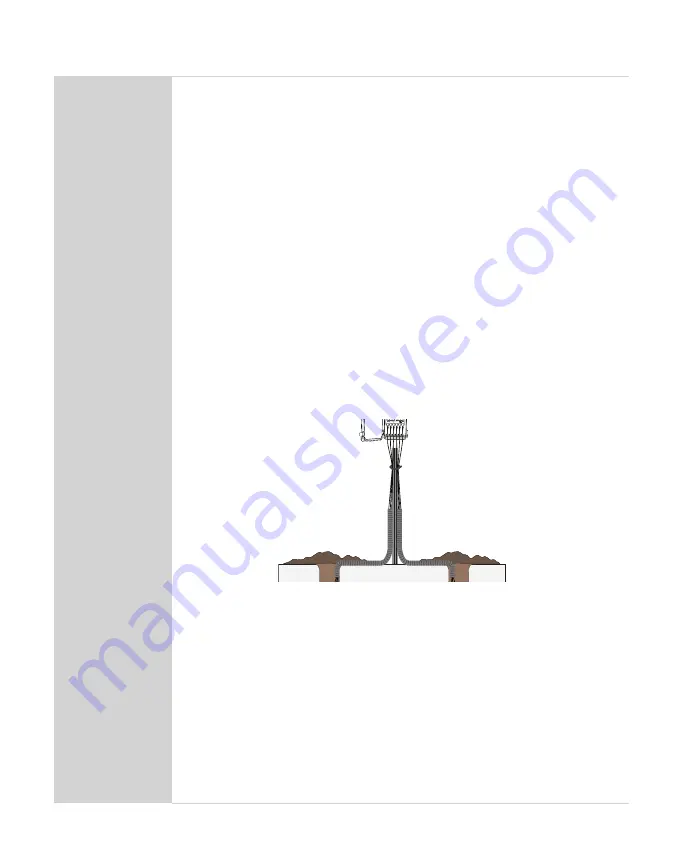
Secure and protect Cables

NOTE:  Improperly protected cables can lead to severed cables or disconnected sensors. 
Cabling issues can be caused by many factors such as rodent damage, driving over sensor 
cables, tripping over cables, not leaving enough cable slack during installation, or poor 
sensor wiring connections. 

Install cables in conduit or plastic cladding when near the ground to avoid 

rodent damage.

Lay the cables in the trench. 

Gather and secure cables between the TEROS 06 and the data logger to the 

mounting mast in one or more places.

Port 1

Port 2

Port 3

Port 4 

Port 5

Port 6

TEST

OK

ERROR 

(-)

(-)

(-)

(-)

(-)

(+)

(-)

(+)

(+)

(+)

(+)

(+)

Connect to Logger 
Plug the sensor into a data logger.

Use the data logger to make sure the sensor is reading properly.

Verify that these readings are within expected ranges.

For more specific instructions on connecting to data loggers, refer to 

Section 2.3

NOTE:  Electrical installations must comply with the safety and EMC requirements of the 
country in which the system is to be used.

Backfill the Soil 
Return soil to the hole and trench in the order it was removed. Pack the soil 

back to its native bulk density.

Содержание TEROS 06

Страница 1: ...1 Connect to METER Data Logger 5 2 3 2 Connect to a Non METER Data Logger 6 2 4 Communication 8 2 5 Removing the Sensor 9 3 System 10 3 1 Specifications 10 3 2 Components 13 4 Service 14 4 1 Calibrat...

Страница 2: ......

Страница 3: ...ture at specified depths following World Meteorological Organization WMO recommendations TEROS 06 is designed for measurements in the field in lysimeters and in water bodies The small diameter of 20 m...

Страница 4: ...in Table 1 to set up the TEROS 06 and start collecting data Table 1 Installation Tools Needed TEROS 06 auger Dead blow hammer PVC casing or flexible conduit to protect cables Cable inserting tool if...

Страница 5: ...driving over sensor cables tripping over cables not leaving enough cable slack during installation or poor sensor wiring connections Install cables in conduit or plastic cladding when near the ground...

Страница 6: ...th a dead blow hammer until the auger head is 30 cm in the ground Continue to check the level for a proper upright angle until the auger is in far enough that the angle does not change 5 Rotate the au...

Страница 7: ...nector wiring used with METER loggers 1 1 2 2 3 3 4 4 Male plug on sensor cable Female plug on connecting cable Figure 3 4 pin M12 plug connector used with non METER loggers 2 3 1 CONNECT TO METER DAT...

Страница 8: ...s 3 Wire it directly into the data logger This option has the advantage of creating a direct connection with no chance of the sensor becoming unplugged However it then cannot be easily used in the fut...

Страница 9: ...has the M12 plug connecting cables connect the TEROS 06 wires to the data logger as illustrated in Figure 6 and either Figure 7 or Figure 8 depending on the desired protocol Connect the screen thick...

Страница 10: ...a bus use the METER ZSC and the METER ZENTRA Utility Mobile app to change the sensor SDI 12 address See the individual sensor integrator guide for more information about the SDI 12 protocol in the se...

Страница 11: ...ING THE SENSOR To remove the sensor from the soil pull gently on the sensor shaft until the sensor is out of the soil WARNING Do not pull by the cable Doing so may break internal connections and make...

Страница 12: ...terface DDI serial communications protocol SDI 12 communications protocol RS 485 two wire serial interface M12 connector only tensioLINK serial communications protocol Modbus RTU communications protoc...

Страница 13: ...connector NOTE If a stripped and tinned wire is needed please contact Customer Support ELECTRICAL AND TIMING CHARACTERISTICS Supply Voltage VCC to GND Minimum 3 9 VDC continuous Typical Maximum 28 0 V...

Страница 14: ...t Drain While Asleep Minimum NA Typical 80 0 mA Maximum NA Power Up Time DDI Serial Ready Minimum 210 ms Typical NA Maximum 400 ms Power Up Time SDI 12 Ready DDI Disabled Minimum 210 ms Typical NA Max...

Страница 15: ...cm high stainless steel ring and the digital sensor is mounted at the inner surface of the stainless steel ring The stainless steel rings have thermal contact to the soil and they transmit the soil te...

Страница 16: ...ntact Customer Support Table 2 Troubleshooting the TEROS 06 Problem Possible Solutions Data logger is not recognizing sensor If using a METER logger update logger firmware Check the logger configurati...

Страница 17: ...day 8 00 to 17 00 Central European time Email support europe metergroup com sales europe metergroup com Phone 49 89 12 66 52 0 Fax 49 89 12 66 52 20 Website metergroup de If contacting METER by email...

Страница 18: ...ta acquisition system See installation connecting the TEROS 06 E email address 15 F fax number 15 I installation 2 connecting the TEROS 06 4 6 mounting 3 tools required 2 M measurements 10 12 measurem...

Отзывы: