


3
INSTALLATION THROUGH SIDE WALL
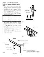
1. Locate the area where the chimney section is to penetrate
the vertical wall. Cut and frame an opening so that
the flue is centered between the vertical wall studs on 6”,
7” and 8” systems. Note that 10”, and 12” systems may
require relocation of wall studs to maintain 2” clearance
to combustibles. Consult local authorities if structural
modifications are required. Frame opening per
FIG. 5
and
Table 2
.
TABLE 2
CHIMNEY FLUE DIAMETER
6”
7”
8”
10”
12”
A
12-7/16”
13-7/16”
14-7/16”
17”
19”
B
13”
14”
15”
17”
19”
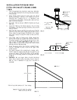
2. A wall firestop (TGWFSP) must be installed in framed
opening from the outside. Push remaining half through
opening from inside until plate is flush. Use four (4) #10 x
2 ½” wood screws to attach to opening. (See
FIG. 6
).
3. Remove wall support adaptor from TGWS box and attach
adaptor to bottom of tee by inserting into bottom of tee and
rotating to lock.
4. Insert the side tap of the tee into the opening in the wall
firestop.
5. Assemble right and left gusset to support plate using
hardware provided.
6. Attach wall support plate to wall support adaptor using 4
clamps provided. Do not tighten. (See
FIG. 6a
).
7. Align wall support with wall and secure to wall studs using
5/16” x 2” lag screws (not provided).
DO NOT SECURE TO
SIDING.
For masonry walls, use 5/16” x 2” masonry lag
bolts.
8. Install tee cap to bottom of wall support adaptor with a
minimum of two (2) #10 x ½” sheet metal screws.
9. Position tee and adapter on wall support to maintain
2” clearance to combustibles. TIGHTEN CLAMPS.
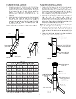
10. Slip a trim sleeve joint cover (TGTS) over the male end of
TG pipe that is to reach through the wall firestop to the tee.
Attach single wall adapter (TGPSWA) to the female end of
TG pipe and slip TGTS flush to the end of TGPSWA. (See
FIG. 7a
and
7b
.)
11. Slide Metal-Fab chimney pipe into top of tee. Align male
and female ends. Push down on pipe sections and turn
clockwise to lock. Additional chimney sections are added
and locked to a MAXIMUM OF 60 FEET. As sections are
added, it will be necessary to secure them to the outside
wall with bands (TGWB) at eight-foot intervals and 2” from
combustibles. Wall bands (TGWB) are secured to the
chimney by placing band around the chimney and tightening
clamping bolt. The assembly is anchored to the wall studs
(not the siding) with 5/8” x 2” lag bolts. To complete the
chimney installation, see “Flashing Installation” and
“Termination” sections.
A
B
FIG. 5
L944 FIG06A
LEFT
GUSSET
RIGHT GUSSET
(ATTACH GUSSETS TO
WALL STUDS USING 5/16”
X 2” LONG LAG SCREWS)
WALL SUPPORT ADAPTOR ASSEMBLY (1 EA.)
CLAMPS (4 EA.)
SUPPORT PLATE (1 EA.)
10-32 HEX NUTS & MACHINE SCREWS
SUPPLIED WITH TGWS (8 EA.)
TGTS
TGSWA
TG PIPE
TGSWA
ALIGN FLUSH WITH
EDGE OF TGSWA
TG PIPE
TGTS
FIG. 7b
FIG. 7a
AIR CLEARANCE 2”
TO COMBUSTIBLES
CHIMNEY TEE
(CAT. NO. TGT)
WALL SUPPORT
ADAPTOR
WALL SUPPORT
(CAT. NO. TGWS)
TEE CAP SUPPLIED
WITH TGT
WALL FIRESTOP
(CAT. NO. TGWFSP)
CHIMNEY PIPE
(CAT. NO. TG)
SINGLE WALL
ADAPTOR
(CAT. NO. TGSWA)
SINGLE OR
DOUBLE
WALL BLACK
STOVE PIPE
6 INCH MIN.
THRU WALLS
L
L=18” FOR SINGLE WALL BLACK STOVE PIPE
L=6” FOR DOUBLE WALL BLACK STOVE PIPE
FIG. 6
FIG. 6a


