


ENGLISH
en
9
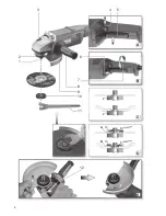
See page 2.
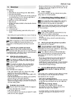
1 Spindle
2 Autobalancer support flange (non-detachable)
3 Spindle locking button
4 Lock (to prevent the machine from being switched
on unintentionally, or for continuous operation)*
5 Trigger ( for switching on and off)
6 Button (to turn the main handle)*
7 Main handle
8 Additional handle / Additional handle with vibration
damping *
9 Safety guard
10 Clamping nut *
11 2-hole spanner *
12 Lever (to adjust safety guard without the use of
tools)
* depending on equipment/not in scope of delivery
Before plugging in, check to see that the rated
mains voltage and mains frequency, as
specified on the rating label, match your power
supply.
6.1 Attaching the additional handle
Always work with the additional handle
attached (8)! Manually screw in the additional
handle securely in the left, centre or right threaded
hole (depending on requirements).
6.2 Attaching the safety guard
(for work involving grinding wheels)
For reasons of safety, the safety guard (9)
should always be attached when roughing
work is performed.
For reasons of safety, the special parting
guard should always be attached before
parting work is performed (see chapter 11.
Accessories).
See illustration E on page 2.
- Push and hold the lever (12). Place the safety
guard (9) in the position indicated.
- Release the lever and turn the safety guard until
the lever engages.
- Push the lever and turn the safety guard until the
closed section is facing the operator.
- Make sure that the guard is seated securely: the
lever must engage and you should not be able to
turn the safety guard.
6.3 Rotatable main handle
Only work with the main handle (7) engaged.
See illustration B on page 2.
- Push in the button (6).
- The main handle (7) can now be turned 90° to both
sides and can be engaged.
- Make sure that it is securely positioned: the main
handle (7) must be engaged and it should not be
possible to move it.
6.4 Power supply
The mains sockets must be protected using time-
delay fuses or circuit breakers.
Disconnect the mains plug before changing
any accessories. The machine must be
switched off and the spindle at a standstill.
For reasons of safety, attach the parting guard
before performing parting work (see chapter
11. Accessories).
7.1 Locking the spindle
Press in the spindle locking button (3) only
when the spindle is stationary!
- Press in the spindle locking button (3) and turn the
spindle
(1) by hand until you feel the spindle locking
button engage.
7.2 Placing the grinding wheel in position
See illustration C on page 2.
The Autobalancer support flange (2) is
permanently fitted on the spindle. As is the
case with most other angle grinders, a detachable
support flange is not necessary.
The contact surfaces of the Autobalancer
support flange (2), grinding wheel and the
adjusting nut (10) must be clean. Clean if
necessary.
- Place the grinding wheel on the Autobalancer
support flange (2) (see illustrations above).
The grinding wheel must lie flat on the
Autobalancer supporting flange. The metal flange
on the parting grinder discs must lie flat on the
Autobalancer support flange.
7.3 Securing/Releasing the clamping nut
Securing the clamping nut (10):
The 2 sides of the clamping nut are different. Screw
the clamping nut onto the spindle as follows:
See illustration D on page 2.
-
A) For thin grinding wheels:
The edge of the clamping nut (10) faces upwards
so that the thin grinding wheel can be attached
securely.
B) For thick grinding wheels:
The edge of the clamping nut (10) faces
downwards so that the clamping nut can be
attached securely to the spindle.
- Lock the spindle. Turn the clamping nut (10)
clockwise using the 2-hole spanner (11) to
secure.
5. Overview
6. Commissioning
7. Attaching the grinding wheel


