


15
VENTING
NOTICE: All vertical and horizontal venting arrangements for Tubular Duct Furnaces are Category III venting.
ANSI now organizes vented appli-
ances into four categories.
Category I
Includes non-condensing appliances
with negative vent pressure, like the
traditional atmospheric unit heater.
Category II
Groups condensing appliances with
negative vent pressure.
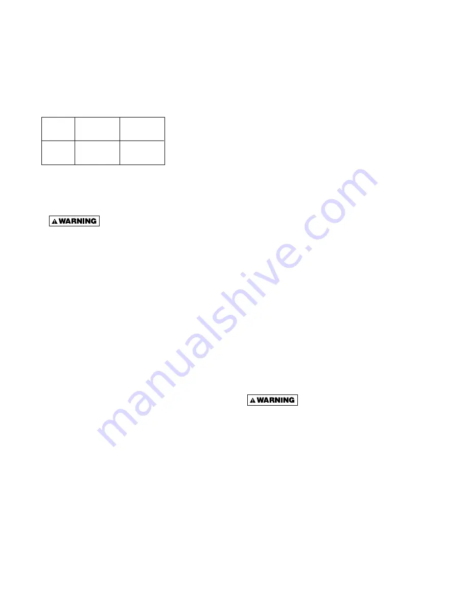
Venting Categories
Non
Condensing
Condensing
Negative
Vent
I
II
Pressure
Positive
Vent
III IV
Pressure
All duct furnaces must be vented! All venting installations shall be in accordance with the latest edition of Part 7,
Venting of Equipment of the National Fuel Gas Code, ANSI Z223.1 (NFPA 54), or applicable provisions of local
building codes. Refer to Figures 8A, 8B, 9A, 9B, 10A, 10B, 11A, and 11B. For installations in Canada, see page 16.
CARBON MONOXIDE! Your venting system must not be blocked by any snow, snow drifts,
or any foreign matter. Inspect your venting system to ensure adequate ventilation exists at all times!
Failure to heed these warnings could result in Carbon Monoxide Poisoning (symptoms include grogginess,
lethargy, inappropriate tiredness, or fl u-like symptoms).
Do not damper or add heat recovery devices to the fl ue piping. Failure to open such a damper prior to operating gas
unit will result in the spillage of fl ue gas into the occupied space.
Category III
Appliances are non-condensing and
operate with a positive vent pressure.
Category IV
Covers condensing appliances with
positive vent pressure.
VENTING FOR POWER VENTED DUCT FURNACES (CATEGORY III)
Maintain 6 inch (152mm) between vent pipe and
combustible materials. A minimum of 12 inch (305mm)
of straight pipe is required from the venter outlet before
installing an elbow in the vent system. An elbow should
never be attached directly to the venter!
Never use a pipe of a diameter
other than that specifi ed in Table 1! Never use
PVC or other nonmetallic pipe for venting! To do
so may result in serious damage to the unit,
severe personal injury, or death.
Any run of single wall vent pipe exposed to cold air or
passing through an unheated space must be insulated
with insulation suitable to 550°F (288°C).
The vent system must be installed to prevent collection
of condensate. Vertical vent pipes should be equipped
with condensate drains. Pitch horizontal pipes downward
1/4 inch per foot (21mm/m) toward outlet for condensate
drainage.
ALL DUCT FURNACES MUST BE VENTED! All venting
installations shall be in accordance with the latest edition
of Part 7, Venting of Equipment of the National Fuel Gas
Code, ANSI Z223.1, or applicable provisions of local
building codes for power vented units. Also see page 16
for additional Canadian installation information.
Vent pipe material must be in compliance with UL 1738
for installations in the United States, and UL S636 for
installations in Canada.
Refer to Table 6 for vent termination clearance require-
ments.
Through the wall vents for these appliances shall NOT
terminate over public walkways, or over an area where
condensate or vapor could create a nuisance or hazard
or could be detrimental to the operation of regulators,
relief valves, or other equipment.
The vent pipe equivalent length must be 5 feet (1.5m)
minimum and must not exceed 50 feet (15.2m). Equivalent
length is the total length of straight sections PLUS 10 feet
(3.05m) for each 90 degree elbow, and 4 feet (1.22m) for
each 45 degree elbow.


