Meridian DSP320 Скачать руководство пользователя страница 7

EN

DSP320 User Guide

EN

Front and back panel
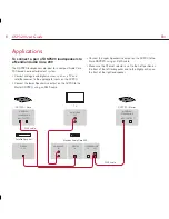
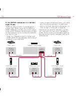
Connections

The following diagram gives details of the connections on 
the back of the loudspeaker:

SpeakerLink

output     input

Power

Use this connection

To connect to this

SpeakerLink input

The SpeakerLink output of a Meridian 
Audio Core or Digital Surround 
Controller.

SpeakerLink output

The SpeakerLink input of a second 
DSP320 digital loudspeaker, when 
connecting in a daisy-chain.

Power

A captive power cord to connect to the 
RF300 rough-in box power outlet.

Front panel

The following diagram gives details of the front of the 
loudspeaker:

Right

Mono

Left

Fuse

~50-60Hz T5.0AH

250V for 100-230V~

CAUTION:

Disconnect supply before changing fuse.

Replace with same type fuse.

ATTENTION:

Débrancher avant de remplacer le fusible.

Utiliser un fusible de rechange

du même type.

On

Off

I

O

II

Channel

selector

Status indicator

and IR receiver

Fuse

Power
switch

Switch

Description

Channel selector

Set to Left or Right to specify the 
position of each loudspeaker, or Mono 
for a mono mix.

Standby indicator

Status

Description

Blue

Loudspeaker in standby.

White

Loudspeaker operating. 
At power-up flashes once if IR is off and 
twice if IR is on.

The loudspeakers are switched on or into standby as appropriate 
via the SpeakerLink connections by the Meridian system they 
are connected to. 

To configure the IR receiver

Hold down one of the following keys on an MSR remote (not 
supplied) while powering up the speaker:

Next

: Turns on IR; white LED flashes twice. 

Previous

: Turns off IR; white LED flashes once. 

Stop

: Resets all to factory settings; white LED flashes 3 times. 

Содержание DSP320

Страница 1: ...DSP320 DSP Loudspeaker User Guide ...

Страница 2: ...nly This apparatus has been designed with Class 1 construction and must be connected to a AC supply socket outlet with a protective earthing connection the third grounding pin The DSP320 must be connected to an earthed AC supply socket outlet An all pole AC supply switch with a contact separation of at least 3mm in each pole shall be incorporated into the electrical installation on the building Sa...

Страница 3: ...in Box Installation Instructions as appropriate Contents Each DSP320 loudspeaker is supplied with the following components DSP320 trim frame DSP320 grille with scrim 3mm Allen key 3mm hex driver 4 x M5 button head screws for speaker 2 x grille extractor keys The loudspeaker can be installed either with or without the trim frame according to user preference as explained on the following pages Insta...

Страница 4: ...rame is clamped in place by loudspeaker cabinet Clamping screws M5 x 10 Holding the loudspeaker carefully Drop the trim frame onto the back of the loudspeaker Plug in the RJ45 cable s and AC supply Slide the loudspeaker into position Fix with M5 x 10 button head screws 4 pieces ...

Страница 5: ...To fit the loudspeaker without the trim frame Clamping screws M5 x 10 Holding the loudspeaker carefully Plug in the RJ45 cable s and AC supply Slide the loudspeaker into position Fix with M5 x 10 button head screws 4 pieces ...

Страница 6: ...To fit the scrim and grille Grille Scrim Magnet positions Lay the scrim into the back of the grille Carefully locate one edge of the grille Lift the grille into position Magnets will grab the grille and hold it in position ...

Страница 7: ...with same type fuse ATTENTION Débrancher avant de remplacer le fusible Utiliser un fusible de rechange du même type On Off I O II Channel selector Status indicator and IR receiver Fuse Power switch Switch Description Channel selector Set to Left or Right to specify the position of each loudspeaker or Mono for a mono mix Standby indicator Status Description Blue Loudspeaker in standby White Loudspe...

Страница 8: ... output on the AC200 to the Master DSP320 using an RJ45 cable Connect the upper SpeakerLink output on the AC200 to the Slave DSP320 using an RJ45 cable Make sure the Channel selector is set to the Left position on the front of the left loudspeaker and to the Right position on the front of the right loudspeaker Meridian Audio Core 200 TV MERIDIAN SPEAKERLINK INPUT OUTPUT MERIDIAN SPEAKERLINK INPUT ...

Страница 9: ...e G65 to each of the remaining loudspeakers using RJ45 cables Make sure the Channel selector on each loudspeaker is set to the Left Right or Centre position as appropriate Alternatively you can connect the loudspeakers using daisy chain wiring connect the front and rear L loudspeakers to the G65 and then link each pair of loudspeakers together by connecting the output from the L loudspeaker to the...

Страница 10: ...NTROL IN DIGITAL IN OUT Distributor 3 3 3 MERIDIAN SPEAKERLINK INPUT OUTPUT RS232 CONTROL IN Control input Control input Control input RJ45 cable RJ45 cable SPEAKERLINK OUT RJ45 cable SPEAKERLINK IN SPEAKERLINK IN RJ45 cable RJ45 cable SPEAKERLINK OUT DSP320 Wall or ceiling DSP320 Wall or ceiling DSP320 Hallway mono DSP320 Hallway mono SPEAKERLINK IN RJ45 cable SPEAKERLINK OUT DSP320 Dressing room...

Страница 11: ...o Mono mode An ideal source for the system is a Meridian Media Source 200 Connect the SpeakerLink output from the Media Source 200 to the SpeakerLink input of the first Distributor 3 module Connect the digital output from the first Distributor 3 module to the digital coax input of the second Distributor 3 module Connect the Meridian DSP loudspeakers to the SpeakerLink outputs of each module Connec...

Страница 12: ...DSP320 User Guide 12 EN ...

Отзывы: