background image


- 7 -


6  Mykerinos Block Diagram 

6.1  Mykerinos Block Diagram 


SSI 


SDRAM 

Up to 32 MB  

Trimedia 
TM-1300 

PLL 

Video 

Control Signals only  

DIFFERENT SIGNALS  


M

IN

D

IN


8

 P

O

S


Figure 1 - Mykerinos Block Diagram 


The Mykerinos board is based on the Philips Trimedia TM-1300 Chip and its associated SDRAM running at 144 MHz. The 
other peripherals are: 


1 FPGA (Field Programmable Gate Array), used to manage the control signals 


1 Timecode reader – generator (LTC and VITC) 


1 Video PLL, used to lock to any incoming Video reference such as black-burst PAL, NTSC or Tri-level HDTV 


1 stereo 24 bit 96kHz D/A for onboard audio monitoring. 

 
Up to 64 audio channels are conveyed over the Trimedia high-speed “Video IN” and “Video OUT” buses through connector 

J4


to/from the specific I/O daughter card. 


6.2  Mykerinos On-Board Connectors and Jumpers 

The connectors implemented on the Mykerinos board are as follows: 


JP1 - 

header 1x2, Reserved.


JP2 - 

Video/TC connector 8x2, offering the same functionalities as J2 but for internal connection


JP3 - 

header 1x2, used to connect internally a Video Reference Sync (in lieu of CVS1IN signal)


J2 

-  1 mini Din 8 pins, used to transfer Video and Timecode signals


J3  - 

1 stereo headphone monitoring output 3.5mm mini-jack connector


J4  - 

1 mezzanine connector 32x2, used to connect I/O daughter cards


JP4 - 

75ohm termination for CVS1IN (input from J2, JP2 or JP3)


JP5 - 

75ohm termination for WCKIO (input from J2 or JP2)


JP6 - 

monitoring gain attenuation (-12dB when open) for the left channel 


JP7 - 

monitoring gain attenuation (-12dB when open) for the right channel


Содержание Mykerinos

Страница 1: ...Audio Processing Board User Manual Version DOC 2 11 December 2006 2001 2006 Merging Technologies Merging Technologies Le Verney CH 1070 Puidoux Switzerland Tel 41 21 946 04 44 Fax 41 21 946 04 45 www...

Страница 2: ...erence in a residential installation This equipment generates uses and can radiate radio frequency energy and if not installed and used in accordance with the instructions contained in this manual may...

Страница 3: ...this limited warranty the customer must upon Merging Technologies Inc request return the product to the place of purchase or other local designation for the necessary repairs to be performed If the co...

Страница 4: ...ICS 13 9 MYKERINOS MODULAR I O DAUGHTER CARDS 14 9 1 ADAT I O DAUGHTER CARD 14 9 1 1 Optical I O configuration 15 9 1 1 1 Standalone mode also called Mono board mode 15 9 1 1 2 HDTDM mode 15 9 1 1 3 X...

Страница 5: ...5 11 1 AUDIO FOR VIDEO WITH SONY DIGITAL BETACAM USERS 25 11 2 AUDIO FOR VIDEO WITH SONY ANALOG BETACAM USERS 26 11 3 MERGING TECHNOLOGIES PYRAMIX 4 X DAW SETUP 27 12 MYKERINOS POWER CONSUMPTION 28 12...

Страница 6: ...ce upto 400 MFlops sustained 800 MB s SDRAM interface etc Support for all sampling rates from 32 kHz up to 192 kHz as well as DSD and DXD Open Plug In all C code architecture supporting Surround sound...

Страница 7: ...speed Video IN and Video OUT buses through connector J4 to from the specific I O daughter card 6 2 Mykerinos On Board Connectors and Jumpers The connectors implemented on the Mykerinos board are as f...

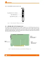
Страница 8: ...nos bracket view The following picture shows a view of the PCI bracket with the monitoring jack and the mini Din connectors Figure 3 Mykerinos Bracket with Jack mini Din connectors U20 U19 U14 U11 U16...

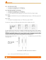
Страница 9: ...ouse sync or black burst reference video signal It is also possible to use this input as a VITC source only standard PAL and NTSC rates Historically all the Mykerinos boards were shipped with jumper J...

Страница 10: ...orrupt the proper decoding of the Video 1 Input signal CVS1IN as well as the Video Output signal CVSOUT This is specifically the case when CVS2IN is used as a word clock I O The Video TC handling sub...

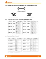
Страница 11: ...from the rear Plug Male 3 1 4 5 2 6 7 8 Total length 100cm Split length 80cm 1 3 4 5 2 6 7 8 Le Verney CH 1604 Puidoux D Baudat MOLDING STRAIN RELIEF Bold Text Text on Label 7 2 Breakout Cable Pin out...

Страница 12: ...N 12600 and MB5 S N 16150 16759 and 16803 Here is a representation of the Video TC bracket Figure 6 Video TC bracket Terminology CVS Composite Video Signal NTSC PAL or HDTV LTC Longitudinal Time Code...

Страница 13: ...ristics The first graph shows the frequency response the THD N 48kHz and the second graph shows the Noise floor FFT 48kHz Figure 7 Monitoring frequency response measurement 130 30 120 110 100 90 80 70...

Страница 14: ...en running in a STANDALONE system the ADAT I O daughter card offers 16 I O channels in ADAT format and or 2 I O stereo channels in SPDIF format SPDIF and ADAT modes use the same optical connectors and...

Страница 15: ...A ADAT Channel 1 8 B C SPDIF Channel 1 2 A ADAT Channel 1 8 B D SPDIF Channel 1 2 A ADAT Channel 9 16 B 9 1 1 2 HDTDM mode INPUT Modes A ADAT Channel 1 8 A ADAT Channel 9 16 B B ADAT Channel 1 8 A AD...

Страница 16: ...oard compliant 9 2 1 Coaxial MADI version connector view Figure 10 Mykerinos coaxial MADI daughter card connectors 9 2 1 1 Coaxial Cable Specifications Merging has conducted internal tests showing rel...

Страница 17: ...ither in the input or output signal path under software control Both single wire 32 to 96 kHz and dual wire 64 to 192 kHz modes are supported under software control Connection is over three DB 25 conn...

Страница 18: ...mode or 4 P3D mode I O of DSD channels through connectors Rear 0 and Rear 1 The AES without SRC provides 8 Sony mode or 6 P3D mode I O of DSD channels through connectors Front Rear 0 and Rear 1 In XD...

Страница 19: ...ns are made using high quality balanced XLR type connectors Provided by two DB 25 breakout cables High quality 24 bit A D and D A using the latest generation in converter technology 2 built in microph...

Страница 20: ...fessional level 4 dBu 9 4 3 Rear 0 connector This DB25 connector is for the DUAL AES EBU I O breakout cable as shown in the following drawing AES EBU IN 1 2 7 8 Any professional level balanced digital...

Страница 21: ...RPLE AOUT3 3 16 AGND 1 20 AGND 1 19 AIN4 2 10 AOUT4 2 4 ANALOG IN 4 YELLOW AIN4 3 22 ANALOG OUT 4 GRAY AOUT4 3 17 Note The DB25 pin 7 is connected to AGND 9 5 2 AES EBU I O breakout cable XLR Label XL...

Страница 22: ...put channels 1 4 ADAT are routed through the AES EBU outputs of the DUA II to the Digital BetaCam inputs The Mykerinos output channels 1 4 ADAT are routed through the analog outputs of the DUA II to t...

Страница 23: ...4 ADAT are routed through the analog outputs of the DUA II to the Analog BetaCam inputs The monitoring is provided by the front panel monitoring selection of the DUA II or through the stereo monitori...

Страница 24: ...AT are routed through the analog outputs of the DUA II to the monitoring system In this example CH1 Left CH2 Center CH3 Right CH4 Subwoofer The Pyramix output channels 5 6 ADAT are routed through the...

Страница 25: ...dphones output the Sphynx analog outputs if analog output modules are installed or the stereo monitoring connector of the Mykerinos board The Sphynx contains at least 2 AES EBU input modules 4 mono in...

Страница 26: ...Mykerinos board The Sphynx contains 2 analog input modules 4 inputs and 2 analog output modules 4 outputs AES EBU output modules are optional in this configuration All units The Mykerinos board via t...

Страница 27: ...8 inputs and 8 outputs in x2 SR mode MERGING PYRAMIX 3 WORKSTATION This example shows the following connections All monitoring is done by the front panel monitoring selection output and or the analog...

Страница 28: ...Typical Boot Typical Boot Typical Unit Current 560 720 630 920 630 950 670 1000 mA Power 2 8 4 3 2 4 6 3 2 4 8 3 4 5 00 W Values Parameter 12 12 Unit Current 80 80 mA Power 1 1 W Note that for the 12...

Страница 29: ...ent 200 150 na na mA Power 1 0 5 na na W 12 6 AES EBU SRC daughter card Values Parameter 5 3 3 12 12 Unit Current 500 150 na na mA Power 2 5 0 5 na na W 12 7 SDIF or TDIF daughter card Values Paramete...

Страница 30: ...ing Technologies SA Le Verney 1070 Puidoux Switzerland Phone 41 21 946 0444 Fax 41 21 946 0445 In the Americas contact Merging USA 43 Deerfield Road Portland ME 04101 1805 United States of America Pho...

Отзывы: