background image

Section 1 - General Information 

Page  4

90-8M0074777   

eng

  MAY  2013

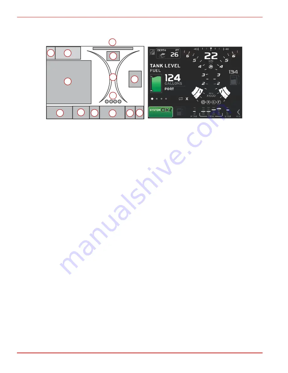
VesselView 7 Screen Display Locations and Descriptions

VesselView has multiple boxes that display specific engine information and active modes.

1

3

4

5

6

7

8

9

10

11

2

12

13

52301 

8

1. Application Swap: Touching this area of the screen will toggle between a Mercury application screen and the last Navico

screen.

2. Volts or Depth: This data box is user definable. A list of all available data parameters is available in the 

Settings

 menu.

The data box will only display voltage when a SmartCraft depth transducer is not installed.

The data box will display depth if a SmartCraft depth transducer is installed.

3. Steering Angle: If installed, the user can select maximum limits of 45 or 60º, and invert the angle. The steering angle will be

available if the installed sensor is connected to the SmartCraft control area network. Steering angle is turned off by default,

but can be manually turned on in the 

Settings

 menu.

4. Speed: Displays the speed of the vessel. If a speed source is not available, the display will show dashes. The display will

show the speed value, the speed source (paddle wheel, pitot, or GPS), and the units of measurement (MPH is the default.)

A speed value greater than two integers will be shown in smaller fonts.

5. RPM: Displays a moving bar representing the engine RPM. A dual‑engine application will show two separate moving bars,

a triple‑engine application will show three, a quad‑engine application will show four.

6. Fuel: This data box displays total fuel.

Displays total fuel only. Individual fuel data will be located in the contextual data area under fuel management.

7. Scroller Bar Icon: Touch this area to show the scroller bar. The scroller bar allows the operator to select different Mercury

application screens to open in the contextual data area.

8. Tabs: This data box is user definable. A list of all available data parameters is available in the 

Settings

 menu.

If installed, Port tab will be displayed on the left side of the trim data. STBD tab will displayed on the right side of the

trim data.

9. Gear Position: DTS products will display all gear positions for each engine. The positions are defined as F = forward, N =

neutral, and R = reverse. Non DTS products will show N = neutral and G for in gear.

10. Trim: This data box is user definable. Displays trim for up to four engines. Trim popup is available in the contextual data

area. Trim popup can be turned off or on in the 

Settings

 menu.

11. Contextual Data Area Icon: Displays an icon representing the data currently being displayed in the contextual data area of

the screen. It will also display the previously displayed contextual data icon if there is currently no contextual data being

displayed. Press the pages button to open the scroller bar. The user can select an icon in the scroller bar and the

contextual data will then be displayed.

12. System Tray: Displays the current active mode and warnings.
13. Contextual Data Area: Displays all contextual data, which includes, for example, initial start‑up scan progress, good

stewardship messages, maintenance schedule, and warnings.

Touch Districts

VesselView 7 incorporates touch‑sensitive districts within the screen. This allows the operator to open or interact with specific

items by using defined touch gestures on the screen. There are two types of touch gestures: tap/press and flick.

Содержание VesselView 7

Страница 1: ... 2013 Mercury Marine VesselView 7 8M0074777 90 8M0074777 513 ...

Страница 2: ......

Страница 3: ...nits Setup 15 Display Screens 16 Startup 16 Engine Off Ignition On 16 Engine Running at Idle 16 Engine Fault 17 Fault Navigation 17 Engine Scheduled Maintenance 18 System Scan Scan Report 18 Communication Errors 19 Section 3 Contextual Data System Tray Functionality 22 Navigation of Contextual Data Display 23 Scroller Bar Functionality 23 Scroller Bar Activation and Navigation 23 Contextual Data A...

Страница 4: ...4 Troll Control Mode 45 Troll Control Contextual Data Area 45 Persistent Data Change 45 Troll Contextual Data Area 45 Troll Navigation 46 Autopilot Screens 46 Autopilot Screens Overview 46 Autopilot Screens Navigation 46 Minimized Autopilot 47 Warnings 47 Popup Warnings 47 Fuel Critical Alarm 48 Depth Alarm 48 Section 6 Installation Mounting Guidelines 52 Mounting Location 52 Electromagnetic Inter...

Страница 5: ...rols Operations 2 Rear Panel 3 VesselView 7 Screen Display Locations and Descriptions 4 Touch Districts 4 Tap Press Districts 5 Flick Districts 6 Color Strategy 7 Maintenance VesselView 7 7 Display Cleaning 7 Stuck Keys 8 How to Update Your VesselView 7 Software 8 Obtaining the Latest Software 8 Backup Your Waypoints Routes and Tracks 8 Upgrading Vesselview 9 1 ...

Страница 6: ...tions All functionality of these piloting features are controlled through a strict protocol with Mercury Marine s autopilot control area network CAN track pad VesselView will show if the mode is active or in standby popups will appear as the vessel arrives at a waypoint asking to acknowledge the turn and display text about how to adjust the engine and drives to achieve maximum efficiency VesselVie...

Страница 7: ... and can be pressed multiple times to toggle through the home page menus A long press displays the Goto menu options In Out MOB Zoom buttons for various NMEA backbone components Pushing the In and Out buttons at the same time will mark the position of the vessel with a man overboard MOB icon Power Standby Brightness Press once to access the standby mode or change the backlighting of the unit or go...

Страница 8: ...will be located in the contextual data area under fuel management 7 Scroller Bar Icon Touch this area to show the scroller bar The scroller bar allows the operator to select different Mercury application screens to open in the contextual data area 8 Tabs This data box is user definable A list of all available data parameters is available in the Settings menu If installed Port tab will be displayed...

Страница 9: ... be accessible The vessel must have a specific Navico device connected to the NMEA 2K backbone to be able to toggle between applications 2 Area that displays data box information 3 Area that displays speed information 4 Area that displays fuel information 5 Area that opens and closes the scroller bar 6 Area that displays data box information 7 Area that displays data box information 8 Area that to...

Страница 10: ...a area 11 Area that performs various tasks for contextual data area Flick Districts Flick districts are used in the contextual data box area and in the Scroller menu bar selection There are two types of flick gestures horizontal and vertical Horizontal flicks will advance the available pages a Pages will advance in the direction of the horizontal flick b When the end of the pages is reached a hori...

Страница 11: ...ext not activated 5 Autopilot not activated 6 Computer controlled function not activated 7 Navigation footer dot highlighted 8 Navigation footer element highlighted 9 Navigation footer element not activated 10 Navigation footer active 11 Tank marker 12 Fuel 13 Oil 14 Water 15 Waste 16 Gray water 17 Good normal 18 Bad warnings Maintenance VesselView 7 IMPORTANT It is recommended that the supplied s...

Страница 12: ...The file is a compressed zip file typically 70 100 MB in size and can take a long time to download on some Internet connections For example estimated download time for dial up 56K modems is 3 4 hrs hours DSL and some cable Internet is 10 15 minutes and high speed cable Internet is 1 2 minutes IMPORTANT A zip file is a compressed file format Your computer may require a free download of Winzip softw...

Страница 13: ... during the upgrade process 1 Verify that the ignition key is off and that VesselView is not turned on NOTE Some installations may have the VesselView powered up with a dedicated circuit rather than by the ignition key on circuit IMPORTANT VesselView must be turned off for more than 5 minutes before upgrading the software 2 Insert the micro SD card into the card reader port all the way until it st...

Страница 14: ...e upload is finished remove the micro SD card and the system will automatically reboot to complete the upload 52758 8 Verify that the software version upgraded is the correct version Use the scroller bar and go to Systems and open About The current software version is listed ...

Страница 15: ...Device Configuration 12 Import Configuration 13 Engine Setup 13 Display Setup 13 Unique VesselView ID 13 Units of Measurement 14 Display Setup 14 Device Setup 14 Units Setup 15 Display Screens 16 Startup 16 Engine Off Ignition On 16 Engine Running at Idle 16 Engine Fault 17 Fault Navigation 17 Engine Scheduled Maintenance 18 System Scan Scan Report 18 Communication Errors 19 2 ...

Страница 16: ...ing that multiple devices are installed The station and display number must be selected through on screen prompts If a personality has never been loaded into the product then VesselView will use the default setup based on what is discovered by querying the SmartCraft protocol for engine and type of drive Further customization can be performed with the onboard menu system Splash Screen When the ign...

Страница 17: ...xt and press enter NOTE If the imported configuration settings are correct for your power package the setup process is complete Engine Setup 1 Use the rotary knob to highlight Engine Type and press the knob to enter 2 Select the type of engine and press the knob to accept Available Types of Engines None 2 Stroke Gas Outboard 4 Stroke Gas Outboard Gas Sterndrive No Troll Gas Inboard No Troll Gas Je...

Страница 18: ...o highlight the engine location Press the knob to turn it off or on VesselView can display information for up to four engines DISPLAY SETUP Select which engines to show on this display Port Previous Next 50722 Stbd 2 Use the rotary knob to highlight which engine to be displayed Press the knob to turn it off or on The following is a description of what may be available depending on the number of en...

Страница 19: ...is configuration setup is complete you can change the type of measurement in the Settings menu Changing the units in the Settings menu will be covered in another section of this manual 1 Press enter and highlight the desired type of measurement 2 Press enter to confirm your selection and highlight Next Press enter UNITS SETUP What units of measure do you want to use Previous Next Selects the gener...

Страница 20: ...is displayed in the contextual data area when the ignition is on and the engines are not running All functions will be available and there will be no engine data displayed The messages are randomly selected Examples include Do you have floatation devices Mercury reminds you to please boat safely The good stewardship list items are subject to change depending on engine type or personality configura...

Страница 21: ...n d Action text e Number of faults Fault Navigation When faults are present they will be identified with numbers along the bottom of the fault contextual tray 1 The selection box will default to the first fault and will have a white filled box with a black number 2 The selected fault will alternate between the fault number and a positive symbol indicating there is more data to display a Number of ...

Страница 22: ...ce 52447 2 Open the icon to expand the text You can reset the maintenance to 100 or exit the screen NOTE The wrench icon maintenance reminder will be displayed in the system tray until the fault is cleared from the system 52448 3 After resetting the maintenance reminder the wrench icon no longer appears in the system tray 52449 System Scan Scan Report When a system scan is completed and there are ...

Страница 23: ...type or personality configuration 51646 Scan complete Good stewardship message Communication Errors When a system scan encounters a communication error the scan will stop and all data fields will be displayed with dashed lines The system tray will be gray with an X in a red circle and text reading Comm Error 51653 Communication error ...

Страница 24: ...Section 2 System Startup Notes Page 20 90 8M0074777 eng MAY 2013 ...

Страница 25: ... Table of Contents System Tray Functionality 22 Navigation of Contextual Data Display 23 Scroller Bar Functionality 23 Scroller Bar Activation and Navigation 23 Contextual Data Area 24 Final Contextual Data Selection 24 Scroller Bar Icons 25 Enlarging Persistent Data 26 Auto Cycle 26 3 ...

Страница 26: ...e System Tray Examples 51875 Engine icon when ignition is turned on The icon is only visible if the power package has emissions control 52099 Communication error when the ignition is turned on The power package is not communicating through the control area network 52100 Indicates that every component connected to the control area network is within normal operating parameters 52101 Warning icon ind...

Страница 27: ... c Level 2 is a standard screen size event for all of the contextual panels d Level 1 is a standard screen size for all contextual data which will include the start up system scan Scroller Bar Functionality The scroller bar provides access to icon items not currently displayed in the contextual data area of the screen The icon item will be hidden until activated and will display the amount of time...

Страница 28: ...s Contextual Data Area During the scroller bar navigation process when the icon is highlighted and enter is not pressed the contextual data area will change to display the icon the icon name and a description of what the feature does The contextual data area will show this information for a short time only Final Contextual Data Selection When the icon has been chosen press enter The icon will show...

Страница 29: ...ge economy volume use per hour total capacity fuel used j Autopilot displays autopilot data k Eco displays information to guide the operator to the best trim position and engine speed to achieve the best fuel economy l Navigation displays data relating to installed navigation system compass heading longitude and latitude time to waypoint TTW bearing to waypoint BTW distance to waypoint DTW course ...

Страница 30: ...ach data box has its own page indicator in the lower left hand corner of the contextual data area Press on the various pages or the auto cycle icon or exit icon Press enter when the auto cycle or exit icon are highlighted a Page indicators b Auto cycle icon c Exit icon Auto Cycle When auto cycle is selected but not active the icon will be displayed on a white field Press the rotary knob to activat...

Страница 31: ... eng MAY 2013 Page 27 Section 4 Setup and Calibrations Table of Contents Settings Menu Navigation 28 Navigation to Settings Menu 28 System 28 Preferences 28 Vessel 29 SmartCraft 29 Easy Links 32 Alarms 32 Units 32 Network 32 Personality File 33 4 ...

Страница 32: ...e version The greater than sign indicates additional menu choices Systems Language Select the desired language Time Change time and date format Automatic time update is only available if a GPS is connected Buzzer Key Beeps Off Quiet Normal Loud Alarm Beeps On checkmark off no checkmark Backlight Level 0 100 Night Mode On checkmark off no checkmark Network Update On checkmark off no checkmark Local...

Страница 33: ...Optional data boxes None One Both Choose type of data for data box 2 Navigation Vessel Engine Environment Scroller Bar Auto hide delay Select 5 10 15 or 30 seconds Item Visibility On checkmark or off no checkmark X PAND temperatures pressure tanks voltages fuel ECO cruise navigation trip log SmartTow troll control engine generator performance and trim and tabs autopilot Startup checklist On checkm...

Страница 34: ... offset zero restore save Speed GPS source CAN P or H Pitot speed source None PCM0 PCM1 PCM2 PCM3 Pitot sensor type 100 or 200 PSI Pitot multiplier Calibration multiplier and restore save Paddle speed source None PCM0 PCM1 PCM2 PCM3 Paddle speed sensor Legacy or Airmar Paddle frequency Calibration multiplier and restore save Steering Steering angle source None PCM0 PCM1 PCM2 PCM3 TVM Invert steeri...

Страница 35: ... Mode timer threshold Set limit 0 10 0 seconds Mode stable threshold Set limit 0 10 0 seconds Steady state threshold Set RPMs per second Limits RPM fuel rate coolant temp oil temp oil pressure water pressure battery voltage intake temp boost pressure transmission oil pressure and temperature Set the limits minimum maximum warning low warning high reset save for each engine Supported data Location ...

Страница 36: ...ugh water rationality fault XTE Waypoint radius Arrival True wind shift True wind high True wind low Fuel remaining low Fuel remaining high Voltage Missing data Vessels Autopilot Engines NOTE These settings must be enabled to receive alarms Show all helm alarms On checkmark off no checkmark Units Units allows you to select the type of measurement for the various SmartCraft network sensors English ...

Страница 37: ... independently from other units You can also globally change all displays to a different source from any display There are ten categories of sources Compass Navigation and Position are a few of the category group sources Under each of these categories a display can be set to receive data from sources as part of the group or receive the data independently from the group 4 Damping Damping allows you...

Страница 38: ...Section 4 Setup and Calibrations Notes Page 34 90 8M0074777 eng MAY 2013 ...

Страница 39: ...ow Overview Panel 40 Smart Tow Contextual Data Area 41 Navigation 41 Save 42 Create Custom Launch 43 Cruise Control Mode 44 Cruise Control 44 Cruise Control Contextual Data Area 44 Persistent Data Change 44 Cruise Contextual Data Area 44 Cruise Navigation 44 Troll Control Mode 45 Troll Control Contextual Data Area 45 Persistent Data Change 45 Troll Contextual Data Area 45 Troll Navigation 46 Autop...

Страница 40: ...h a short description on how to achieve the best fuel economy ECO Minimum and Maximum Values When ECO Mode is active the minimum and maximum value target lines will appear in the RPM sweep These lines display the active optimized range that is to be calculated The target lines can be adjusted in the Settings menu 52167 ECO RPM and Trim Targets When the RPM values reach the minimum value range RPM ...

Страница 41: ...tructions to displaying OPTIMIZED with the current fuel economy value 52174 ECO Navigation The contextual data area footer will display REFRESH MINIMIZE and X Minimize will hide ECO instructions and display ECO MODE in the system tray Minimize allows the user to display other information in the contextual area Refresh will reset the ECO values and use new parameters for determining the RPM and tri...

Страница 42: ...tual data area will show instructions and show new target values on how to achieve optimization for the best economy Minimize Minimize is a feature that allows the user to continue with the ECO features while displaying additional information in the contextual data area 1 When minimize is selected the ECO instructions will be removed and then display additional information in the contextual data a...

Страница 43: ...ility 0 7 seconds RPM stability 0 7 seconds RPM window minimum 2000 RPM RPM window maximum 4000 RPM RPM target proximity 10 Trim target proximity 3 IMPORTANT A manual trim calibration must be performed before the ECO screen can be used if a vessel personality was not uploaded with a micro SD card Using a default trim calibration will not allow the ECO screen to function properly Changing Target Va...

Страница 44: ... Active Orange Solid 52183 When Smart Tow is not active the RPM sweep display is white Smart Tow will modify the color of the RPM sweep display to orange when active 52184 Active RPM sweep display color orange Smart Tow Overview Panel Smart Tow will display an overview panel before launching Smart Tow for the first time This screen will remain visible for a short time The overview panel provides i...

Страница 45: ...ong the launch path showing what part of the launch sequence the system is performing LAUNCH 2 52188 Launch graph animated dot Navigation Smart Tow utilizes the contextual data area and the footer section to allow you to adjust the settings Press or flick to move through the selection box fields The footer section allows you to enable or disable Smart Tow save or exit There are five selection fiel...

Страница 46: ...n After making adjustments to the desired settings press the selection in the footer area of the contextual data area Enable or disable turns the feature on or off The persistent data RPM sweeps will be displayed as non active white sweeps The operator can modify all settings when the system is in the off disabled state a Enabled on is green when active b Disabled off is red when not active a Not ...

Страница 47: ...he main screen without saving the new data Create Custom Launch Create custom launch allows the operator to create a custom launch profile The operator can adjust the set point of the RPM or speed ramp overshoot and overshoot duration When the operator selects this option the contextual data area will transition to the custom profile set up screen 52286 Use the rotary knob to move the selection bo...

Страница 48: ...mode is activated elements of the persistent data will be modified to communicate RPM set point RPM sweep color will change to orange when active to indicate the engine is computer controlled a Cruise not active b Cruise active Cruise Contextual Data Area Cruise will modify the contextual data area of the screen when active Elements within the contextual data area will change to allow the user to ...

Страница 49: ...ll automatically fill the contextual data area The operator will have to minimize to hide the popup data 5 After minimize is activated the system tray will display CRUISE 6 When exit is selected while displaying cruise element the cruise feature will be disabled The cruise icon will be displayed next to the system tray until another icon is selected from the scroller bar Troll Control Mode The tro...

Страница 50: ...e b If autopilot is active and troll is minimized the system tray will display TROLL in the system tray Troll data will be displayed over autopilot settings if the user selects the system Tray If an autopilot popup warning occurs or the operator uses the autopilot CAN track pad autopilot contextual data will automatically fill the contextual data area The operator will have to minimize to hide the...

Страница 51: ...rack auto waypoint sequence or standby Waypoint sequence will be displayed on a field of orange in the system tray all other modes will be on a field of gray Warnings Popup Warnings All Mercury warning alarms will be shown regardless of what screen is displayed at the time of the warning When an alarm warning is activated the status box will display the warning text and icon Faults along with thei...

Страница 52: ...ed as a persistent data field location 2 but it is active as a warning fault then the system tray will display a red field and show FUEL The operator can also select the fuel warning as a contextual popup in the Settings menu Pressing the rotary knob will minimize the contextual panel The fault will still be displayed in one of two locations depending on the screen set up Depth Alarm The depth ala...

Страница 53: ... 2013 Page 49 The operator can also show the depth warning as a contextual popup in the Settings menu Pressing the rotary knob will minimize the contextual panel The fault will still be displayed in one of two locations depending on the screen set up ...

Страница 54: ...Section 5 Screen Navigation Notes Page 50 90 8M0074777 eng MAY 2013 ...

Страница 55: ... Page 51 Section 6 Installation Table of Contents Mounting Guidelines 52 Mounting Location 52 Electromagnetic Interference 52 Installing VesselView 7 52 VesselView 7 Wire Harness 53 VesselView NMEA 2K Connections 54 VesselView 7 Cut out Template 55 6 ...

Страница 56: ...lView is not mounted closer than 1 5 m 5 ft from a radio or transmitting mast 2 m 6 5 ft from a radar antenna 1 m 3 ft from a compass Installing VesselView 7 The following installation instructions have been written for the harnesses included with the VesselView The 90 harness connectors may not allow VesselView to be installed when the dashboard thickness is greater than the dimension listed Stra...

Страница 57: ... Harness a SmartCraft network connection b Power connection c Video in d SIMNET NMEA 2000 e Ethernet network f VesselView 7 adapter harness g System Link port h Air temperature sensor i System Link starboard j Horn k System Link starboard center l System Link port center m Junction box a b c d e f g h i j k 52774 l m ...

Страница 58: ...EA 2K must be powered separately from the SmartCraft network The NMEA 2K power supply must be properly fused and have termination resistors at each end of the backbone a 120k ohm termination resistor b GPS c Chart plotter d NMEA 2K fused power source e VesselView 120 a a b c d e e 52795 120 ...

Страница 59: ... 90 8M0074777 eng MAY 2013 Page 55 VesselView 7 Cut out Template IMPORTANT Due to printing and copying variables the image size may have changed from the actual size Check the graphic for accuracy prior to using the template ...

Страница 60: ...Section 6 Installation Page 56 90 8M0074777 eng MAY 2013 52866 a b c d e f ...

Страница 61: ...Section 6 Installation 90 8M0074777 eng MAY 2013 Page 57 a 212 7 mm 8 37 in b 140 5 mm 5 53 in c 214 2 mm 8 43 in d 142 1 mm 5 59 in e 4 3 mm 0 17 in 4x f 25 mm 0 98 in ...

Отзывы: