Nr dok: HO.18.00313 EN.doc rew.: B
z dn.: 09.10.2018
Gdańsk, 09.10.2018 r.
Technical and Operating Documentation
User Instruction Manual
Smoke and Heat Exhaust Control Unit
mcr 9705
Страница 1: ...Nr dok HO 18 00313 EN doc rew B z dn 09 10 2018 Gdańsk 09 10 2018 r Technical and Operating Documentation User Instruction Manual Smoke and Heat Exhaust Control Unit mcr 9705 ...
Страница 2: ...pment provided for use within certain voltage limits 2014 30 EU EMC regarding electromagnetic compatibility Related documents European certification of constancy of performance of construction products CNBOP PIB No 1438 CPR 0607 and The Declaration of Performance No 092 HO 2018 of 12 09 2018 confirming the compliance of the power supply with the requirements of EN 12101 10 2007 EU Declaration of C...
Страница 3: ...e following features automatic alarm release by a signal from a fire alarm control unit manual alarm release by alarm pushbuttons automatic alarm release by smoke sensors transmitting information about alarm NO NC signal transmitting information about the defect of the system NO NC signal transmitting information about vent opening NO NC signal manual opening of a smoke vents for ventilation of th...
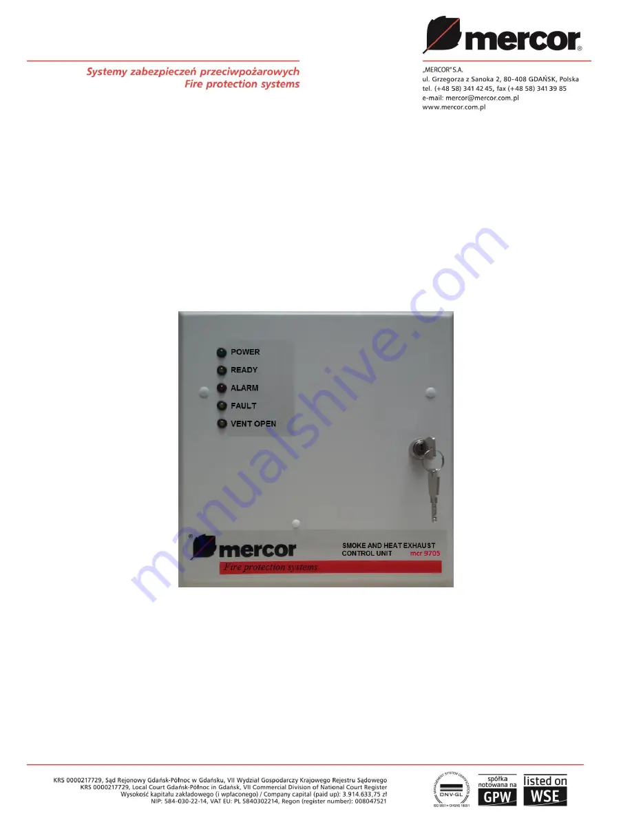
Страница 4: ...tem status READY FAULT ALARM 2 About the mcr 9705 control unit Pic 1 Front panel of a control unit On the front panel there are diodes which indicate the status of the control center No Description Color Function 1 POWER SUPPLY green indicates that both power supplies are present 2 READY yellow indicates no alarm system ready for operation 3 ALARM red optical alarm indicator 4 FAULT yellow general...
Страница 5: ...e actuator line line gap 11 yellow defect to the sensor line line gap 12 yellow defect to the pushbutton line line gap or short circuit 13 not installed 14 yellow not used 15 yellow disconnection of the sensor line SW1 2 16 yellow disconnection of the pushbutton line SW1 3 17 yellow disconnection of the in out connectors providing information about alarm and defect SW1 4 18 green power supply same...
Страница 6: ...ctions of the control unit Switch position Function SW1 1 Disconnection of the actuator line SW1 2 Disconnection of the sensor line SW1 3 Disconnection of the ROP pushbutton line SW1 4 Disconnection of the in out relay contacts SW1 5 Full opening of the vents during non emergency ventilation in in ventilation and hatch mode SW1 6 Activation of the mode door s control SW1 5 SW1 6 Enabling the elect...
Страница 7: ...fect indication output relay contact 38 P16 programmable service output ex opening the vent door closing relay contact 39 P17 RPO 1 indication output 1 2 3 48 P19 power supply for alarm signaling loop Note For control units designed for the purpose of a smoke curtain above the elements 30 44 there is additional 4 poles terminal strip for mcr PROSMOKE CE CE1 curtains actuators There are two additio...
Страница 8: ...constant 230 V mains power supply In case of power shortage caused by mains failure the installed batteries will ensure 72 hour emergency power supply Any power outage exceeding 72 hours can result in permanent damage of the batteries 3 2 Non emergency ventilation daily ventilation For smoke vents equipped with electrical smoke exhaust actuators and the system with ventilation pushbuttons it is po...
Страница 9: ...e in place of the ventilation mode When hatch mode is active the weather station s displays don t cause vent s closing it is not possible to close the vent with the ventilation button the vent opens just like in ventilation mode by pressing the ventilation button the time of opening the damper depends on the settings on the H6 and H5 jumpers the vents Jumper Condition Opening time in ventilation m...
Страница 10: ...is also used to control the operation of mcr PROSMOKE FSv2 CE smoke curtains In this case after cutting off the power from the actuators the curtains automatically fall into the working position NOTE the door automation mode is not intended for the controlling the mcr PROSMOKE CE CE1 curtains In the electric locking drive activating alarm boxes in the ALARM state the control panel gives a fixed 24...
Страница 11: ...tuated by the control unit in the closing direction Then delete the alarm using the RESET button The red ALARM diode will be turned off and the yellow READY diode will light up If the cause of the alarm can t be removed for example when there s an alarm source failure one needs to access the segment representing the relevant alarm source in the SW1 switch in the control centre module Pic 3 item 27...
Страница 12: ... in silicone insulation feature PH30 for example HLGs from P8 terminals Terminal resistor 10 kΩ in the last connection box The line is protected by a 6 3 A or 8 A fuse FS3 The maximum number of actuators in accordance with the technical parameters Only specific leads shall be used leads that are compatible with actual regulations Attention In case of multi module centrals do not connect galvanized...
Страница 13: ...m from one control unit to another use the P14 alarm output terminal and the P13 alarm input terminal with P12 power supply Do not connect output lines to actuators of different modules Control units can be connected together into ventilation sections To do this connect in parallel the P6 ventilation terminals of all control units in a section U up D down ground joint Connect the weather monitorin...
Страница 14: ...t identification possible To test their operation press the TEST button and hold it down for about 1 s To test the operation of the audible alarm indicator press simultaneously the TEST and RESET buttons Note in order to connect the unit you should use leads which satisfy the requirements of current regulations 5 Instruction manual for checking connection and performance of the mcr 9705 control un...
Страница 15: ...e of the proper alarm source with the diode of the button mcr RPO 1 if connected and on the alarm signal output ohmmeter control and all connected fire devices controlled by the control panel should be controlled 9 Check the correctness of the line disconnection signaling on the service panel after switching the segments 1 4 of switch SW1 page 6 the appropriate LEDs should light up on the service ...
Страница 16: ... Elements CP weather monitoring unit mcr P054 LT ventilation pushbutton ŁNK key switch for activating the hatch mode ME electromechanical actuator OCD optical smoke sensor e g KL731 PM connection box RPO manual smoke exhaust pushbutton mcr RPO 1 Attention Not all the elements of the system in particular the fire protection control unit and the weather monitoring unit must be present in the smoke e...
Страница 17: ... advice of a manufacturer RPO manual smoke exhaust pushbutton mcr RPO 1 PM connection box ME electromechanical actuator 24 V curtain mcr PROSMOKE CE CE1 Attention 1 Not all the elements of the system in particular the connection with fire protection control unit must be present in the smoke exhaust system 2 Central unit or module operating with smoke curtain cannot be connected simultaneously to s...
Страница 18: ...KE FSv2 to control unit mcr 9705 central unit in the mode doors control Elements PM connection box MECU XL work controller of smoke curtain mcr PROSMOKE FSv2 CE P service pushbutton for temporary lowering of the curtain Diag 4 An example of connection of external alarm device a with its own power source b without its own power source b a ...
Страница 19: ...gnal between modules or central units Attention 1 Remove jumper H1 in controlled module 2 Controlled module is activated by the alarm signal from steering module 3 The autoreset function in controlled module should be enabled SW1 8 OFF mcr 9705 control unit steering module mcr 9705 control unit controlled module ...
Страница 20: ...s as well as service and warranty activities such as visual inspection or repair it is necessary to provide physical access to the devices It is recommended to perform those check ups in between of inspections 1 Checking the status of signaling of control LEDs 2 Checking the condition of electrical connections paying special attention to looseness and mechanical damage In matters related to techni...
Страница 21: ... or aggressive cleaning products parts liable to natural wear and tear during operation e g seals unless a manufacturing fault has occurred damages due to aggressive external factors especially chemical and biological ones 7 Each defect under guarantee should be reported to a local representative of MERCOR S A immediately i e within 7 days of its discovery 8 Applications can be made by phone at 48...
Страница 22: ...W 16x or G16x or SG16x 3 pcs 5 pcs MCRW 20x or G20x or SG20x 2 pcs 4 pcs MCRW 26x or G26x or SG26x 2 pcs 3 pcs MCRW 40x or G40x or SG40x 1 pcs 2 pcs MCRW 60x or G60x or SG60x 1 pcs MCRW 80x or G80x or SG80x 1 pcs other types of electric actuators depending upon consumed and maximum current Maximum number of electromagnetic door locks by type mcr TE 50 40 pcs 40 pcs mcr TE 100 30 pcs 30 pcs The max...
Страница 23: ...Smoke and Heat Exhaust Control Unit mcr 9705 User Instruction Manual Strona 23 z 24 10 The Declaration of Performance 11 European Certificate of Constancy of Performance ...
Страница 24: ...Smoke and Heat Exhaust Control Unit mcr 9705 User Instruction Manual Strona 24 z 24 ...