background image

DISASSEMBLY INSTRUCTIONS

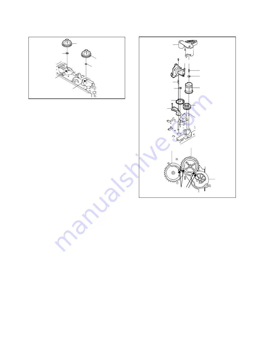
Reel Disk S

Reel Disk T

(A)

(A)

Fig. 2-8

PINCH ROLLER / CASSETTE OPENER
(Refer to Fig. 2-9)

2-9:

Cam Pinch Roller

Cam P5

Arm P5 Ass'y

Cam Pinch Roller

Cam P5

Cassette Opener

Cam Gear

3

Fig. 2-9

Marker

2-10: AUDIO CONTROL HEAD (Refer to Fig. 2-10)

1.
2.
3.

Remove the 3 screws 

1

.

Remove the 3 Audio Control Head Springs.
Remove the Audio Control Head.

Polyslider Washer

Polyslider Washer

Unlock the support 

1

.

Remove the Pinch Roller.
Remove the screw 

2

.

Unlock the 2 supports 

3

.

Remove the Cassette Opener.
Remove the Spring P5 and Arm P5 Ass'y.
Remove the Cam Gear, Polyslider Washer 

4

, Spring

Cam Pinch and Cam Pinch Roller.
Remove the Polyslider Washer 

5

 and Cam P5.

1.
2.
3.
4.
5.
6.
7.

8.

NOTES

1.
2.

Do not touch the Pinch Roller. (Use gloves.)
When installing the Cam P5, Cam Pinch Roller and Cam
Gear, align the timing marks.

Pinch Roller

2

1

3

Spring P5

Polyslider Washer 

5

Cam Gear

Spring Cam Pinch

Polyslider Washer 

4

NOTES

1.

2.

Do not touch the head by any means when replacing the
Audio Control Head. (Use gloves.)
After replacement, confirm the following adjustments.
a. MECHANICAL ADJUSTMENTS: ITEM 2-2
b. MECHANICAL ADJUSTMENTS: ITEM 2-3

B2-3

Содержание MVT2138

Страница 1: ...OVD 5 DATE OF ISSUE 12 1997 Parts on the deck of our product are very similar as shown below Make sure to use the parts listed by Parts No in the service manual for the repair because the deck or your...

Страница 2: ...R T ASS Y CLUTCH GEAR S ASS Y AHC ASS Y CAM PINCH ROLLER P5 ARM ASS Y CATCHER P5 2 MAIN CHASSIS ASS Y ROD MAIN ASS Y CAM P5 The following parts can not be distinguished by the external appearance SPRI...

Страница 3: ...ME MODE SWITCH PART NO 0520244003 or 0520244006 Distinction You can distinguish by the cut part Cut part 2 NAME HOLDER TENSION S PART NO 85OP400452 NAME HOLDER TENSION PART NO 85OP400359 Distinction Y...

Страница 4: ...ME CAM MAIN PART NO 85OP600535 Distinction You can distinguish by the shape in the dotted circle NAME WORM VP ASS Y PART NO 85OA600179 NAME WORM ASS Y PART NO 85OA600159 Distinction You can distinguis...

Страница 5: ...78 NAME MAIN BRAKE T ASS Y PART NO 85OA600156 Distinction You can distinguish by the shape NAME LEVER MAIN BRAKE VP PART NO 85OP600530 NAME LEVER MAIN BRAKE PART NO 85OP600468 Distinction You can dist...

Страница 6: ...ACKET BRAKE PART NO 85OP600471 Distinction You can distinguish by the shape in the dotted circle NAME ARM IDLER VP ASS Y PART NO 85OA200067 NAME ARM IDLER ASS Y PART NO 85OA200065 Distinction You can...

Страница 7: ...here is no step There is a step 6 The following parts can t be distinguished by the external appearance CLUTCH GEAR S ASS Y and CLUTCH GEAR S S ASS Y CLUTCH GEAR S VP ASS Y and CLUTCH GEAR S VPS ASS Y...

Страница 8: ...P400433 MATERIAL COLOR WHITE Distinction You can distinguish by the material color and the dent NAME P5 ARM ASS Y PB PART NO 85OA400168 NAME P5 ARM ASS Y PART NO 85OA400120 Distinction You can disting...

Страница 9: ...2 Distinction You can distinguish by the shape NAME MAIN CHASSIS ASS Y PART NO NAME MAIN CHASSIS ASS Y PART NO Distinction You can distinguish by the shape in the dotted circle 85OA000173 85OA000221 8...

Страница 10: ...00181 NAME ROD MAIN ASS Y PART NO 85OA600176 NAME ROD MAIN VPS PART NO 85OP600538 NAME ROD MAIN VP PART NO 85OP600527 Distinction You can distinguish by the shape in the dotted circle RATCHET PLATE Ba...

Страница 11: ...10 NAME CAM P5 PART NO 85OP400450 NAME CAM P5 PART NO 85OP400344 Distinction You can distinguish by the tooth height of circled section All teeth are the same height Only one tooth is high...

Страница 12: ...SERVICE MANUAL Design and specifications are subject to change without notice MVT2138 ORIGINAL MFR S VERSION C COLOR TELEVISION VIDEO CASSETTE RECORDER...

Страница 13: ...ther there are the portions which are deteriorated around the serviced places serviced or not Check the insulation between the antenna terminal or external metal and the AC cord plug blades And be sur...

Страница 14: ...CRT SYSCON OPERATION SCHEMATIC DIAGRAMS TIMER MICON IF CHROMA SOUND AMP DEFLECTION CRT POWER TV OPERATION 2 Y C AUDIO HEAD AMP IN OUT SYSTEM CONTROL SERVO POWER VCR OPERATION 1 INTERCONNECTION DIAGRAM...

Страница 15: ...ESECAM Yes No G 8 Cassette Tape VHS type video cassette tape Width 12 65mm 1 2 Inch VHS C type video cassette tape Width 12 65mm 1 2 Inch G 9 Tape Speed NTSC or PAL M PAL or SECAM SP 33 35 mm sec SP 2...

Страница 16: ...19 Stereo Dual TV Sound Yes NICAM GERMAN USA JAPAN No G 20 Video Signal Input Level 1 Vp p 75 ohm Output Level 1 Vp p 75 ohm S N Ratio 50 dB Weighted Horizontal Resolution at SP Mode 230 Lines G 21 Au...

Страница 17: ...ding System G 30 Tape Counter Linear Time Tape Counter G 31 Protector Power Fuse Dew Sensor G 32 Regulation Safety UL CSA SAA SI CE SEV BS NF NEMKO FEMKO DEMKO IEC65 SEMKO NZ HOMOLO SABS CNS SISIR NOM...

Страница 18: ...On Screen Display Menu Clock Set Calendar 12H 24H Timer Rec Set Language Auto Repeat On Off Area Code On Off Timer Set Channel Set Guide CH Set Picture ATS System Select Protect On Off User Registrati...

Страница 19: ...daptor Rod Antenna One Pole Two Pole F Type DIN Type France Type Loop Antenna F Type DIN Type France Type U V Mixer Quick Set up Sheet DC Car Cord Center Battery UM 4 x 2 Guarantee Card AC Cord Warnin...

Страница 20: ...2 Play Set 3 F Fwd Set 4 Rew Auto Ch Memory 5 Pause Still Delete 6 Stop Add 7 Eject Tracking Auto 8 Slow Tracking Up 9 Clock Counter Tracking Down 10 Counter Memory Call 11 Counter Reset TV Caption T...

Страница 21: ...e the Anode Cap Refer to REMOVAL OF ANODE CAP Disconnect the following connectors CP820 CP810 CD850 CP401 CD840 and CP502 Slide out the TV Block in the direction of arrow B Front Cabinet TV Block B CR...

Страница 22: ...D4002 CP1004 and CP4106 Remove Chassis Section in the direction of arrow B 2 3 Syscon PCB Chassis Section 4 4 5 1 1 1 Case Shield A B Front Loading Unit 15 4 5 Fig 1 6 A NOTE When installing the Front...

Страница 23: ...emove the Locker R Cassette Side L Cassette Side R Link Ass y 3 Cassette Holder Ass y Bracket R Spring 3 2 2 Side Bracket R1 Joint Gear 2 2 1 1 Side Bracket L Fig 2 2 NOTES When installing the BOT Lev...

Страница 24: ...Ass y A Fig 2 7 Tension Arm Spring 2 NOTE 1 2 Install the Tension Band Ass y without twisting it Turbine Oil Lubricating Grade 150 the area marked with A in Fig 2 7 EX KYOUDO Oil Sulaidasu 150 IDEMIT...

Страница 25: ...he 2 supports 3 Remove the Cassette Opener Remove the Spring P5 and Arm P5 Ass y Remove the Cam Gear Polyslider Washer 4 Spring Cam Pinch and Cam Pinch Roller Remove the Polyslider Washer 5 and Cam P5...

Страница 26: ...ove the Polyslider Washer 2 4 Remove the Center Pulley Spring 5 Remove the Idler Arm Ass y 6 Remove the 2 Polyslider Washers 3 7 Remove the Clutch Gear T Ass y and Clutch Gear S Ass y Clutch Gear T As...

Страница 27: ...an Brake Ass y Remove the Tension Holder Remove the Tension Lever Remove the Main Cam Remove the Middle Gear Remove the Main Rod Ass y NOTES 1 2 When installing the Main Rod Ass y install side B first...

Страница 28: ...p up the sides of the Rubber Cap in the direction of the arrow and remove one side of the support Refer to Fig 3 2 2 GND on the CRT Screwdriver Alligator Clip Support CRT GND on the CRT Rubber Cap CRT...

Страница 29: ...linder Cylinder Motor Cylinder Sensor Data Syscon to Servo Decibel Direct Current Direct Drive Motor Unit Demodulator Detector Deviation Emitter Emitter Follower Emphasis Encoder Envelope End of Tape...

Страница 30: ...or Separation Transistor Tracking Trick Playback Test Point Unregulated Volt Voltage Controlled Oscillator Video Intermediate Frequency Vertical Pulse Voltage Display Video Playback Variable Resistor...

Страница 31: ...r Refer to the figure below 2 TAPE RUNNING SYSTEM When cleaning the tape transport system use the gauze moistened with isopropyl alcohol 3 CYLINDER Wrap a piece of chamois around your finger Dip it in...

Страница 32: ...mode by setting VOLUME to minimum While holding down VOLUME button on front cabinet press key 6 on remote control simultaneously ADDRESS and DATA should appear as FIG 1 4 5 6 7 8 9 The unit will now...

Страница 33: ...oller S Ass y P0 Post P1 Post FE Head Cylinder Unit Auto Head Cleaning Audio Control Head 11 12 13 14 15 16 17 18 19 20 Loading Motor Ass y Pinch Roller Block Cam Gear Cassette Opener Brake Bracket Re...

Страница 34: ...28 29 30 31 32 Capstan Brake Ass y Bottom Plate Clutch Gear S Ass y Idler Arm Ass y Center Pulley Clutch Gear T Ass y FRONT LOADING UNIT 15 1 2 3 4 5 6 7 8 Side Bracket L Top Bracket Ass y Side Bracke...

Страница 35: ...4 Remarks Monoscope 6KHz Color Bar 1KHz Playback Take Up Torque Fast Forward Torque Rewind Torque Brake Torque Take up Reel Supply Reel Guide Roller Adjustment X Value Adjustment Reel Disk Height Adju...

Страница 36: ...Disk Height Adjustment Jig JG024 Height Adjustment Washer 3 1x5 4xT0 13 3 1x5 4xT0 3 Reel Disk Height Adjustment Jig JG024 Reel Disk Master Plane JG022 7 5mm 0 2 B A Turn on the power and set to the...

Страница 37: ...erance replace the appropriate parts as follows 2 TAPE RUNNING CONFIRMATION AND ADJUSTMENT Check Items Replace Parts 1 4 Idler Ass y or Clutch ASS Y 1 5 Idler Ass y or Clutch ASS Y 1 6 Main Brake T As...

Страница 38: ...the screw 3 Refer to Fig 2 2 until the height of the A C head reaches the position against the tape as shown in Fig 2 3 When the control head height is not correct When you must turn the screw more t...

Страница 39: ...RED BIAS GREEN BIAS BLUE BIAS RED DRIVE GREEN DRIVE BLUE DRIVE NEXT 1 2 3 4 5 6 7 8 H PHASE V DC V SIZE OSD H CUT OFF NEXT 8 8 Use the 1 8 keys on the remote control to select the options shown in Fi...

Страница 40: ...oscope pattern Using the remote control set brightness to normal position and set contrast to maximum position Activate the adjustment mode display of Fig 3 1 and press the channel button 1 on the rem...

Страница 41: ...tton on the remote control to select AV input Press the VOL UP DOWN button on the remote control until the white 10 is starting to be visible ELECTRICAL ADJUSTMENTS 4 7 E SUB TINT TV 1 2 3 4 Receive t...

Страница 42: ...of purity magnets Switch the color bar generator from the green raster pattern to the crosshatch pattern Combine red and blue of the 3 color crosshatch pattern on the center of the screen by adjustin...

Страница 43: ...MAJOR COMPONENTS LOCATION GUIDE MAIN CRT T501 VR 502 TP802 TP803 TP801 J801 FOCUS VOLUME SCREEN VOLUME CP401 TV SECTION FB401 C528 J503 D4 1...

Страница 44: ...MAJOR COMPONENTS LOCATION GUIDE SYSCON TP4201 J4201 TU651 CP830 L601 L603 TP4101 TP4102 TP1002 TP1001 VCR SECTION D4 2...

Страница 45: ...MONITOR_V_OUT Q516 P CON 9V DRICER Q502 CR2AM 8 F8 Q517 P CON SW SAW FILTER CF603 1 4 3 10 Q505 ERROR AMP Q503 11 3VREG VIDEO IN 29 38 Q609 BUFFER Q604 BUFFER 61 BLUE BACK H Q607 B B SW 11 IF 4 5 SDA...

Страница 46: ...4003 Q4004 AUDIO PB AUDIO REC ENV DET AUDIO PB Q4012 PHASE EQ TRICK_PB H SP L LP M EP H Q4011 BIAS SW Q4010 BIAS OSC L4005 5 1 VIDEO_IN AUDIO_IN IN OUT P R Y C AUDIO IC4001 LA71022M 46 BIAS 15 TV VCR...

Страница 47: ...LOADING MOTOR DRIVE IC1002 OEC9029A 11 TRICK PB H TRICK_PB H 73 SP L LP M EP H 1 2 8 VCC CP1002 5 3 1 CYL DRIVE CYL FG CYL PG CAPSTAN DD UNIT TV 34 33 LDM FWD LDM REV 35 53 DRM ON DFG IN 54 DPG IN 3 V...

Страница 48: ...8 7 4 2 3 1 5 Q4212 BUFFER Q4207 SW Q4205 Q4206 TUNER MUTE SW MONITOR_V_OUT MONITOR_A_OUT AUDIO_IN TUNER_A_OUT J4201 TV Y C AUDIO HEAD AMP Y C AUDIO HEAD AMP SYSCON SERVO OPERATION IN OUT BLOCK DIAGRA...

Страница 49: ...112 C438 R521 C403 R413 R471 W038 W114 W116 W037 R417 W829 W055 W051 W056 W057 R535 S108X S108Y W119 W018 C546 D405 W115 W830 C541 W031 W108 C540 W012 W083 C811 R813 R814 R811 C809 R820 R807 C812 C821...

Страница 50: ...1050 W090 W162 W160 W827 W166 R692 W006 W010 R1070 R162 C1037 W041 C1036 W360 W390 W011 C667 C4011 C4049 R1019 C1023 R1041 W329 C126 W119 W103 W243 W222 W341 W340 C1007 R4003 R4104 R1054 W175 C4010 C6...

Страница 51: ...01 Q1002 R1008 R1009 R1075 R1021 C101 R163 Q102 W829 W004 W005 W817 W814 W804 W835 W838 C4210 R1069 C4064 C4039 C4054 R4037 C4078 W819 C4129 W259 R108 R1010 C1033 R1046 R107 R628 R610 C613 R618 R614 W...

Страница 52: ...SW772 SW775 SW776 SW777 SW778 SW779 D753 D754 D757 CD757 R771 R772 C781 C779 R754 R753 R757 R766 W805 R775 R777 R776 R778 C755 C751 W001 OS751 W803 D756 R756 F 7 F 8 PRINTED CIRCUIT BOARDS OPERATION...

Страница 53: ...KS OF PRINTING AND SUBJECT TO CHANGE WITHOUT NOTICE NOTE THIS SCHEMATIC DIAGRAM IS THE LATEST AT THE TIME Q105 2SC2412K SWITCHING Q104 2SC2412K SWITCHING Q107 2SC2412K BUFFER Q100 2SC2412K V SYNC DRIV...

Страница 54: ...TILISER QUE CELLS DECRITES DANGEREUSES AN POINT DE VUE SECURITE ETANT LES PIECES REPAREES PAR UN ATTENTION C667 2 2 50V KA OF PRINTING AND SUBJECT TO CHANGE WITHOUT NOTICE NOTE THIS SCHEMATIC DIAGRAM...

Страница 55: ...AL FOR SAFETY USE ONES ARE SINCE THESE PARTS MARKED BY CAUTION DANS LA NOMENCLATURE DES PIECES N UTILISER QUE CELLS DECRITES DANGEREUSES AN POINT DE VUE SECURITE ETANT LES PIECES REPAREES PAR UN ATTEN...

Страница 56: ...TF C439 0 056 630V PP C435 0 012 630V PP C438 0 0022 2KV BP C412 390P 500V B C411 0 1 100V TF C413 0 001 M C532 6 8 250V ECQ E C550 4 7 250V ECQ E C437 0 033 M C444 100P 500V B C406 0 0022 M C475 2200...

Страница 57: ...01 B C810 470P B C821 68P SL C812 68P SL C809 560P B C802 10 50V YK DESCRIBED IN PARTS LIST ONLY CRITICAL FOR SAFETY USE ONES ARE SINCE THESE PARTS MARKED BY CAUTION DANS LA NOMENCLATURE DES PIECES N...

Страница 58: ...531 0 001 125V MX C506_1 0 22 250V MMCA C518 470P 500V B C544 0 068 M C516 0 0047 500V B C517 0 01 TF C546 0 1 TF C549 0 01 B C501 0 0022 500V B C503 0 0022 2KV B C502 0 0022 2KV B C533 0 0033 125V MX...

Страница 59: ...SKHVBED010 PLAY SW777 SKHVBED010 VOL DOWN GND B Vout OS751 GP1U281R 1 2 3 CD757 CH2A012A 1 10 2 3 4 5 6 7 8 9 R757 270 R754 330 R756 390 R775 820 R778 820 R772 1 5K R777 1 5K R771 1K R776 1K R766 100...

Страница 60: ...W147 W988 W293 W989 W414 W906 W827 W941 W826 W829 L4007 1mH 0607 L4006 100uH0607 L4008 100uH 0607 L4003 100uH 0607 PF4001 2623003 15 6KHZ TRAP 1 2 3 4 6 L4004 68uH L4002 220uH L4001 150uH L4011 270uH...

Страница 61: ...IS THE LATEST AT THE TIME DURING PLAYBACK MEASURED WITH THE DIGITAL TESTER NOTE THE DC VOLTAGE AT EACH PART WAS W819 W854 W805 L4102 100uH L4101 22uH SP L LP M EP H H SW ENV DET V REC_ST H GND PB Y C_...

Страница 62: ...AGRAM IS THE LATEST AT THE TIME DURING PLAYBACK MEASURED WITH THE DIGITAL TESTER NOTE THE DC VOLTAGE AT EACH PART WAS Q4206 2SC2412K MUTE SWITCH Q4207 2SC2412K VIDEO OUT SW Q4202 2SC2412K EXT IN SW W9...

Страница 63: ...W900 W882 D1004 11E1N D1005 11ES1N D1009 1SS133 D1014 11ES1N D1007 1SS133 D1008 1SS133 X1001 16MHz CP1005 8283_0212_00_000 1 2 CD1004 2L051101 FFC CORD JUMPER LDM LDM GND AT 5V CYL_PG CTL CTL CYL_PG...

Страница 64: ...P CON SW W994 W993 L1001 10uH0607 Q1005 2SB892 P CON 5V DRIVER Q1012 2SB892 P CON 9V DRIVER P CON 9V P CON 5V A P CON 5V A AT 5V VCR_POWER H GND P CON 5V A AT 5V AT 5 6V AT 12V GND MOTOR_GND GND AT 12...

Страница 65: ...EMATIC DIAGRAM IS THE LATEST AT THE TIME W843 W830 W938 W822 W937 D705 11EQS04N AT 5 6V GND PLAY_LED T REC_LED REC_LED GND REMOCON_OUT TV_POWER H KEY A KEY B GND FROM TO TIMER MICON FROM TO SYSCON SER...

Страница 66: ...CK CD351 CP354 SOUND GND SOUND OUT 3 2 1 TO OS701 TM101 COMMAND TRANCMITTER SOUND OUT SOUND GND MICRO MOTOR CYLINDER UNIT DC JACK LDM B LDM B DEW DEW SENSOR DEW SENSOR GND GND CP4101_1 CH2 L F VIDEO H...

Страница 67: ...the corresponding balloon number in the schematic diagram NOTE DEFLECTION 1 20V 5ms div 2 5V 20 s div 3 5V 20 s div 4 5V 5ms div CRT 5 50V 20 s div 6 50V 20 s div 7 50V 20 s div 8 200mV 20 s div 9 50...

Страница 68: ...c diagram NOTE 20 REC 0 3V P P Y C AUDIO 16 REC 0 5V P P 17 PB 0 51V P P 18 REC 0 5V P P 19 PB 100mV 20 s div 25 REC 1V 1ms div 24 REC 1V 1ms div 23 REC 500mV 5 s div 22 PB 20mV 5ms div 21 REC 0 34V P...

Страница 69: ...of the corresponding balloon number in the schematic diagram NOTE 31 REC PB 20mV 5ms div 32 REC PB 2V 5ms div 32 REC PB 0 5V 5ms div 33 REC PB 0 5V 0 2ms div 34 REC PB 20mV 0 5ms div 35 REC PB 1V 10m...

Страница 70: ...WAVEFROMS H 4 The following waveforms were measured at the point of the corresponding balloon number in the schematic diagram NOTE 45 REC 500mV 50ms div 46 REC 500mV 50ms div...

Страница 71: ...216 217 148 217 217 217 207 216 103 104 102 101 113 114 113 114 218 111 112 SP354 PCB390 EARPHONE PCB ASS Y J352 A 107 108 202 202 109 106 105 110 116 117 118 115 218 201 PCB030 OPERATION PCB ASS Y P...

Страница 72: ...CHANICAL EXPLODED VIEW A 141 206 144 143 205 208 142 TU651 139 134 138 135 140 136 208 137 209 PCB010 SYSCON PCB ASS Y 145 147 215 215 215 215 211 210 210 213 211 146 214 214 212 216 I 2 151 207 150 2...

Страница 73: ...301 302 303 310 512 311 312 321 316 309 304 305 316 313 319 320 503 308 322 M101 503 323 504 511 324 325 329 515 327 307 326 334 338 337 335 340 336 516 339 516 509 333 332 331 330 UN4001 M2003 H5001...

Страница 74: ...D VIEW BOTTOM VIEW 342 M2001 344 346 352 351 348 349 350 347 345 366 364 365 506 515 359 517 361 362 367 355 356 353 354 357 357 507 504 503 358 343 369 SW101 502 502 504 506 341 363 504 504 306 306 5...

Страница 75: ...FRONT LOADING UNIT 15 EXPLODED VIEW 421 403 420 404 407 405 401 410 408 421 416 417 406 409 419 425 402 415 412 411 411 424 422 413 414 422 423 426 418 I 5...

Страница 76: ...CREW TAPPING B0 FLAT 4x12 118 7220001107 SHEET HWC 206 8117330A04 SCREW TAPPING B0 FLAT 3x10 119 7230006603 FILM DECORATION 207 8107230602 SCREW TAP TITE S BIND 3x6 208 8117540B04 SCREW TAPPING B0 TRU...

Страница 77: ...333 85OP200217 REEL T 507 8109126804 SCREW TAP TITE B PAN 2 6x8 334 85OP400446 CATCHER P5 VP 508 82Q3154B3N POLYSLIDER WASHER 3 1x5 4xT0 13 335 85OP600465 SUB BRAKE S 509 810A130604 SCREW WASHER A M3...

Страница 78: ...102M CE 1000 UF 35V VZ D532 D2BT0EG01Z DIODE SILICON EG01Z V0 C406 P1S300222J CP 0 0022 UF 50V D601 D1VT001330 DIODE SILICON 1SS133T 77 C415 E02LF3102M CE 1000 UF 25V D602 D97U07R51B DIODE ZENER MTZJ7...

Страница 79: ...ANSISTOR SILICON 2SC945 C T P Q L4102 021673101K COIL 100 UH Q604 T8YA2412K0 TRANSISTOR SILICON 2SC2412KT147 R S L4205 021673101K COIL 100 UH Q606 T8YJ2412K0 TRANSISTOR SILICON 2SC2412KT146 R S T401 0...

Страница 80: ...OR CH22070A CD4106 122L061101 CORD JUMPER 2L061101 CP1001 0697150310 CONNECTOR PCB SIDE TAS X05X D1 CP1002 06CH24055A CORD CONNECTOR CH24055A CP1003 06972A0580 CONNECTOR PCB SIDE TKC G10P A1 CP1004 06...

Страница 81: ...SPEC NO M512 86P W935029 O R NO...

Отзывы: