DISASSEMBLY INSTRUCTIONS
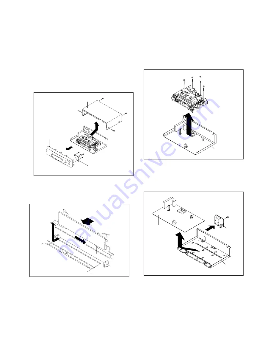
1. REMOVAL OF MECHANICAL PARTS
AND P.C. BOARDS
1-1: TOP CABINET, FRONT CABINET AND
OPERATION PCB (Refer to Fig. 1-1)
1.
2.
3.
4.
5.
6.
Remove the 4 screws
1
.
Remove the Top Cabinet in the direction of arrow (A).
Disconnect the following connector: (CP651).
Unlock the 7 supports
2
.
Remove the Front Cabinet in the direction of arrow (B).
Remove the 4 screws
3
and remove the Operation PCB.
1-2: FLAP (Refer to Fig. 1-2)
Open Flap to 90˚ and flex in direction of arrow (A), at
the same time slide in direction of arrow (B).
Then lift in direction of arrow (C).
1.
2.
(A)
(C)
(B)
Flap
Fig. 1-2
1-3: DECK CHASSIS (Refer to Fig. 1-3)
1.
2.
3.
4.
Remove the 3 screws
1
.
Remove the screw
2
.
Disconnect the following connectors: (CP1001, CP1002,
CP1003, CP4001, CP4002 and CP4003).
Remove the Deck Chassis in the direction of arrow.
Bottom Plate
Deck Chassis
Fig. 1-3
1
2
1
1
1-4: SYSCON PCB AND JACK PLATE (Refer to Fig. 1-4)
1.
2.
3.
4.
Remove the screw
1
.
Remove the Syscon PCB in the direction of arrow (A).
Unlock the 2 supports
2
.
Remove the Jack Plate in the direction of arrow (B).
Fig. 1-4
Syscon PCB
(B)
2
2
Bottom Plate
(A)
Jack Plate
1
B1-1
Fig. 1-1
1
Top Cabinet
3
1
1
1
(A)
Front Cabinet
(B)
3
3
3
Operation PCB
2
2
2
2
2
2
2
Содержание MVR2040A C Series
Страница 47: ...M4C8 A1B B034007 SPEC NO O R NO ...


