background image


DMW-22-TDL SERVICE MANUAL


Confidential and proprietary information of Meister Cook, LLC.  Not to be reproduced or used in any manner other than 

with the express written permission of Meister Cook, LLC. 


9

 | 

P a g e


Restoring Factory Defaults 


NOTE:

  this procedure should only be performed with the understanding that any saved 

presets and parameters will be erased.  It is strongly recommended to record any custom 
presets and parameters.


With power turned off to the DMW, press and hold 

Bin 1

.


Turn on the DMW while holding 

Bin 1

.  A series of beeps will indicate that the defaults have 

been restored.


4.


REVISION HISTORY 

 
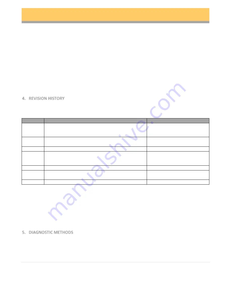
Refer to the chart below for a summary of revisions of the DMW-22-TDL (as of 2015-01-12): 
 

Revision 

Changes 

Serial Numbers 

Original release 
DMW-20027 Rev A Heaters 
V1.26 firmware 

0001 through 0120 

C / C1 

DMW-20027 Rev B Heaters,  
V1.46 firmware 

0121 through 4522 
4523 through 4864 & RMA’s 

C2 

Same as Rev C with V1.49 firmware 

Various RMA’s 

Funnels mount to Cabinet instead of Electronics cover 
DMW-20066 6 pin TC cable 
V1.46 firmware 

4865 to 4937 
(plus 4999 – 5012*)  

D1 

Same as Rev D with V1.49 firmware 

7716 

Original DMW-20031 10 pin TC cable replaces DMW-20066 6 
pin  

4938 to current 

Same as Rev E except V1.49 firmware 

TBD-7715 

 
NOTE:  

other than menu presets, there are no field adjustable firmware parameters.  As of the 

publication of this manual, there have been no observed instances of firmware corruption.  Any 
corrupt user interface or system control functions would require a hardware solution. 


These s/n’s were inadvertently duplicated during production 


5.


DIAGNOSTIC METHODS 

 
As part of troubleshooting, there are several methods that can be used to diagnose reported failures.  
The DMW-22-TDL has a set of on-board fault codes that indicate potential fault conditions: 


FLT! 1111 – missing zero crossings detected 

Содержание DMW-22-TDL

Страница 1: ...DMW 22 TDL SERVICE MANUAL For Systems Installed At Revision 20150414...

Страница 2: ...roduced or used in any manner other than with the express written permission of Meister Cook LLC 2 P a g e TABLE OF CONTENTS 1 INTRODUCTION 3 2 BASIC THEORY OF OPERATION 3 3 OPERATING INSTRUCTIONS 5 4...

Страница 3: ...of time without degrading the quality of the food products The DMW 22 TDL has 2 independently controlled heated holding chambers each which can hold 2 1 3 size food pans Underneath each chamber is a l...

Страница 4: ...185 03 00 00 15 PSTA 185 04 00 01 00 CKS2 185 06 00 01 00 VEG2 185 04 00 01 00 VEG2 185 04 00 00 30 SCEG 185 02 00 00 30 PSTA 185 04 00 01 00 BCHK 200 02 00 00 30 PORK 185 06 00 01 00 CHIP 200 02 00 0...

Страница 5: ...tory defaults note that v1 46 and later systems have both English and French default menus v1 26 Defaults v1 46 v1 49 Defaults English French AM EGGS SCEG AM EGGS SAUS OEUF SAU2 SAUS BACN HSBR HSBR GL...

Страница 6: ...ides for optimal efficiency and performance Plug the DMW into a 120V 60Hz 20 amp circuit fitted with a properly grounded NEMA 5 15 outlet A couple of precautions Make sure that 7 5A are available per...

Страница 7: ...etpoint controls the chamber temperature Allow the DMW 25 35 minutes to preheat Basic Operation NOTE after 10 seconds of inactivity the UI will time out and return to the home display To display the c...

Страница 8: ...tion To save changes and exit the Preset Edit menu press and hold Prog The save will be confirmed by 2 beeps To exit the Preset Edit menu without saving changes press AM PM To edit a preset s timers P...

Страница 9: ...1 DMW 20027 Rev B Heaters V1 46 firmware 0121 through 4522 4523 through 4864 RMA s C2 Same as Rev C with V1 49 firmware Various RMA s D Funnels mount to Cabinet instead of Electronics cover DMW 20066...

Страница 10: ...ntended to indicate a failed heater as well as prevent the heater from overheating in the event of a fault in the movement of air and or temperature control circuit However certain installation condit...

Страница 11: ...is guide will be updated Also note if the recommended steps do not resolve the problem escalate to the next level Finally be sure to document all symptoms reported and unreported all corrective action...

Страница 12: ...power draw Check blowers for sufficient rotation Check blower wheel for proper vane orientation Check thermocouples for o Contamination on tips o Damage to wire o Short circuit o Crossed connections...

Страница 13: ...off the system have operator unplug system from outlet Verify no obvious foreign objects are present Check for presence of foreign objects Check for damage to wire harnesses Check for short circuits T...

Страница 14: ...B POWER SUPPLY W 10 PIN THERMOCOUPLE PCB 1 DMW 20107 PCB THERMOCOUPLE 10 PIN SV 1 DMW 20108 CABLE THERMOCOUPLE SV 2 DMW 20109 SWITCH ROCKER DOUBLE POLE IP65 SV 1 DMW 20110 CORD POWER SV 1 DMW 20111 OV...

Страница 15: ...Description PN Description DMW 20110 Power Cord DMW 20115 Cable Power Supply to Switch to Motor DMW 20116 Cable Heaters to Power Supply DMW 20114 Thermistor DMW 20117 Cable Motor Grounds DMW 20106 PC...

Отзывы: