AVTMTTR25 Rev C April 2008
41
Appendix C
Connections and Vector Voltage Diagrams
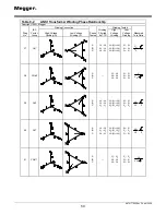
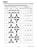
Table C-1 and C-2 show winding diagrams for standard transformers and
nonstandard transformers for power and distribution transformers marked in
accordance with the ANSI standard. Table C-3 shows winding diagrams for
power transformers marked in accordance with the CEI/IEC standard, and Table
C-4 shows winding diagrams for power transformers marked in accordance with
the Australian standard.
To make a measurement on a three-phase power transformer with TTR25 test
set, match the vector diagram from the transformer nameplate to the
corresponding winding connection diagram from Table C-2 through C-4. Then
connect the TTR25 test leads to the appropriate transformer winding terminals of
phase A. Put an external jumper, if required. After phase A test is complete,
reconnect the test leads to phase B. Put an external jumper, if required. After
phase B test is complete, reconnect the test leads to phase C. Put an external
jumper, if required. Compare the measured test results to the calculated turns
ratios.
NOTE. Three phase transformer may be tested in any order. For example, phase
C, then phase A, and then phase B turns ratio may be tested.
The tables show the windings tested for each of the three phases. The tables
also show the relationship between the measured turn ratio and the actual line-
to-line voltage ratio. For the ANSI specification, the rated voltage on the
high-voltage winding is represented by V
H
; V
X
represents rated voltage on the
low-voltage winding.
Содержание TTR25
Страница 2: ......
Страница 3: ...TTR25 Handheld TTR Transformer Turn Ratio Test Set Instruction Manual...
Страница 14: ...M AVTMTTR25 Rev C April 2008 6 M...
Страница 34: ...M AVTMTTR25 Rev C April 2008 26 M...
Страница 42: ...M AVTMTTR25 Rev C April 2008 34 M...
Страница 78: ...M AVTMTTR25 Rev C April 2008 70 M...


