

NETWORK
ENVIRONMENTAL
Frame Rate
30 / 25
Video Compression Type
H.264, MJPEG
IP
IPv4,
IPv6
LAN
802.3 Compliance 10/100 LAN
Web Viewer
OS: Windows XP / Vista / 7, MAC OS
Browser: Internet Explorer, Chrome, Firefox, Safari
Video Management Software
DW Spectrum™
Streaming Capability
Multi Streaming CBR/VBR
Power Requirement
DC 12V, PoE (IEEE802.3af Class 2)
Power Consumption
1 92W, 160mA / LED ON: 2.7W, 230mA
Operating Temperature/ Humidity
-10
o
C ~ 50
o
C (14
o
F ~ 122
o
F), Less than 90% Humidity
Dimensions
Ø 125 x 74.3 mm (Ø 4.9 x 2 9 inch)
Material
Aluminum
Housing
Weight
700 g (1.54 lbs)
Maximum User Access
4 Users
MECHANICAL
ELECTRICAL
Resolution
720p/SVGA/D1/VGA/CIF/QVGA/QCIF
IP Rating
IP66 (Protects against dust and high pressure water)
LENS
IMAGE
Image Sensor
1/2 9" 1.0M CMOS
Lens Type
Fixed Lens
Focal Length
2.8mm [DWC-MF10M28T]
3.6mm
[DWC-MF10M36TIR]
8.0mm
[DWC-MF10M8TIR]
IR Distance
30ft Range IR [IR models Only]
20150316
TEL: (866) 446-3595
www.Digital-Watchdog.com / [email protected]
Technical Support Hours: Monday-Friday 9:00AM to 8:00PM EST
DW Desktop Tool™
Use the DW Desktop Tool™ included in the camera’s accessory CD to scan the network and detect all MEGApix cameras.
Use the DW Desktop Tool™ to set the camera’s network settings,perform firmware upgrade or access the camera’s web client
1
2
3
4
5
6
To adjust the camera’s orientation:
1. Loosen the tilt stopper screw at the base
of the camera’s gimbal by rotating it
counter clock-wise.
2. Move the camera to the desired angle.
3. Secure the camera’s lens position by
screwing the tilt stopper screw clock-wise.
Template Sheet
Power
Ethernet cable
Ethernet cable
Two Options
Use a PoE-enabled switch to connect data and power through a single cable and begin
viewing and recording images instantly. A non-PoE switch will require an adapter for
power transmission.
1. Using a PoE-Enabled Switch
The Camera is PoE-compliant, allowing
transmission of power and data via a
single Ethernet cable.
PoE eliminates the need for the different
cables used to power, record, or control
the camera.
Follow the illustration below to connect
the camera to a PoE-enabled switch
using an Ethernet cable.
2. Using a Non-PoE Switch
If a PoE-enabled switch is not used,
use a power adapter for power
transmission and non-PoE switch for
data transmission.
Follow the illustrations below to
connect the camera without a
PoE-enabled Switch.
Cabling
Specifications
Web Viewer Screen
Installation Using Mount Plate
Installation Using Mount Bolt & Nut
Template Sheet
1
3
2
4
5
Detach the camera’s cover dome from the
camera’s module by unscrewing the three
cover dome screws.
Using the metal mount plate, mark and
drill the necessary holes in the wall or
ceiling.
Pull wires through and make connections.
Using the three (3) included screws, mount
and secure the camera to the wall or
ceiling.
Attach the camera base to the metal
mount by snapping it into place using the
two metal handles.
Secure the camera’s cover dome onto the
camera base to complete the installation.
See ‘Disassemble the Camera’ for
water-proof cabling installation.
Detach the camera’s cover dome from the
camera’s module by unscrewing the three
cover dome screws.
Using the camera or mounting template,
mark and drill the necessary holes in the
wall or ceiling.
Secure the two long mounting screws to
the camera’s base.
Pull wires through and make connections.
Mount the camera to the mounting surface
using the 2 mounting nuts.
Secure the camera’s cover dome onto the
camera base to complete the installation.
See ‘Disassemble the Camera’ for
water-proof cabling installation.
1
2
3
4
5
7
6
5
1
2
3
4
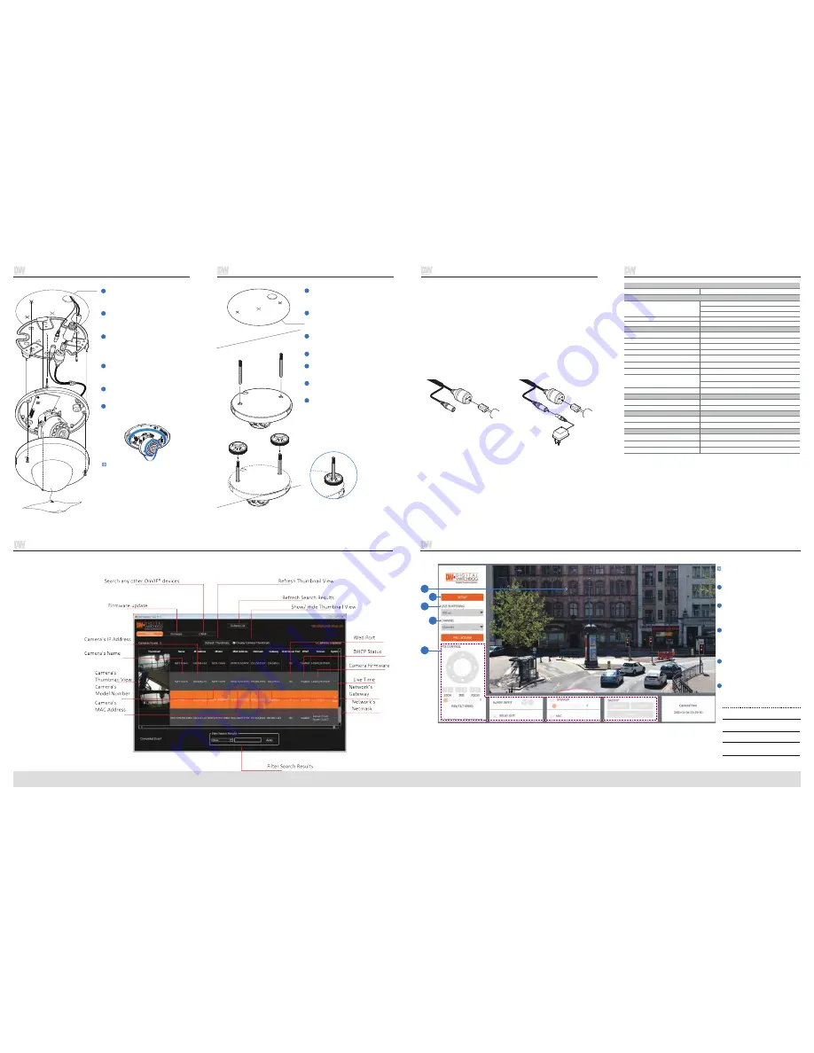
Web viewer is optimized with Internet
Explorer10 or higher and Chrome.
Live video display. This is the region
for live video stream from the camera.
Setup Menu. Click to setup the
camera’s Video, Network, Events,
System etc.
When the image is not smooth
due to a slow network connection,
you can setup the buffering time to
make streaming video smoother.
PTZ Control- Virtual control for PTZ cameras.
ALARM Control- Control sensor inputs and
relay outputs on supported cameras.
Backup- Export or print video and images from
the camera on supported models.
Sound Control- Control audio to and from the
camera on supported cameras.
Stream selection button. Select a
stream from the camera’s 3 available
streams to display it in the viewing area.
Menu options such as PTZ, audio, sensor
and backup options will be disabled for
cameras that do not support those
functions.


