MEE TSD-CT194-CN Скачать руководство пользователя страница 9


画面調節

9

 5 画面調節

画面の調節方法として「自動画面調節」と「マニュアル画面調節」の 2 種類があります。

本機をコンピュータと接続し

たときは、最初に「自動画面調節」をおこなってください。

その後、調節をおこなう必要がある場合は、

「マニュアル画面調節」

をおこなってください。

  本機は水平周波数:30.0  〜 80.0kHz  、垂直周波数:50 〜 75Hz  対応となっていますが、この範囲内であって

も入力信号によっては表示できない場合があります。その場合は、コンピュータのリフレッシュレートまたは解像
度を変更してください。

1. 自動調節

(1) 本機、およびコンピュータの電源を入れてください。

(2) OSD メニュー内の「Auto  Image」を選択することにより、自動画面調節を開始します。入力された信号を検出し、

「Display  Width」、「Phase」、「H-Position」、「V-Position」の自動調節を開始します。自動調節中は「Auto  Ad-

just Image」の文字が表示されます。

 画面の調節

2. マニュアル調節

(1) 本機およびコンピュータの電源を入れてください。

(2) 次項の「OSD 機能」を参照のうえ、調節項目を選択します。

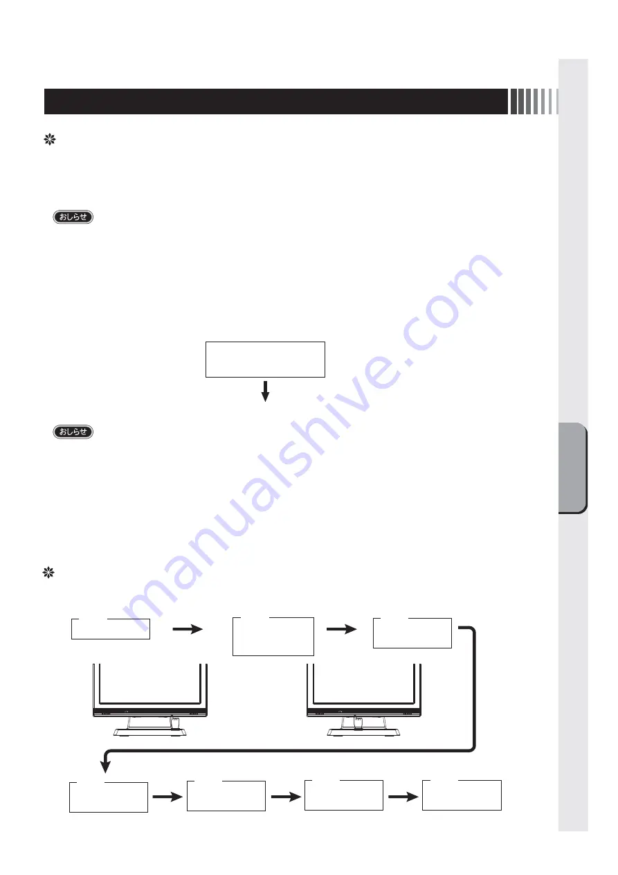
(3) 調節ボタンを押してお好みの画面に調節します。

手順③

「−」

「+」ボタンで調節

グループを選択する。

手順①

本機の電源を入れる。

SELECT/INPUTボ
タンで項目を選ぶ。

手順④

「−」

「+」ボタンで調

節項目を選択する。

手順⑤

SELECT/INPUTボ
タンで項目を選ぶ。

手順⑥

「−」

「+」ボタンで調

節する。

手順⑦

その他、OSDで操作方法を表示している場合は
それに従ってください。

手順②

本体前面にある
MENU/EXITボタンを
押してOSDを表示する。

OSD機能

本機にはOSD(On Screen Display)機能がついていますので、OSD画面により画面の調節などができます。

Auto Adjust

Image

自動画面調節中

自動調節終了

(アナログ接続の場合)

  DOS プロンプトのように文字表示のみの場合は、自動画面調節がうまく機能しない場合があります。

  コンピュータやビデオカードによっては、自動画面調節がうまく機能しない場合があります。

この場合、マニュアル画面調節でお好みの画面に調節してください。

Содержание TSD-CT194-CN

Страница 1: ...2 3 6 6 7 7 OSD 8 8 8 9 9 9 14 14 16 16 17 17 18 19 11 11 11 12 http www mee co jp sales visual touch monitor 19 TSD CT194 CN...

Страница 2: ...2 VCCI B VCCI WindowsNT Windows Vista Windows Microsoft Corporation Macintosh Apple Inc...

Страница 3: ...3 AC100V AC100V...

Страница 4: ...4 During servicing disconnect the plug from the socket outlet...

Страница 5: ...5 This Touch monitor is designed for use in Japan and can not be used in any other countries 40 70cm OA...

Страница 6: ...6 SELECT INPUT OSD OSD P10 MENU EXIT OSD OSD SELECT OSD OSD OSD OSD OSD 1 OSD OSD OSD OSD SELECT MENU EXIT SELECT INPUT P11...

Страница 7: ...7 Kensington D Sub15 D Sub 9 RS 232C DVI D DVI D CAC DV2D 2m AV 352 2m DVI D 24 DVI D DVI D RS 232C D Sub 15 D Sub 15 2 CD ROM D sub 9 D sub 9...

Страница 8: ...socket outlet shall be installed near the equipment and shall be easily accessible AC100V 1 0A RS 232C DVI VGA 2 4 5 DVI D 3 5 3 D Sub 15 D Sub 9 DVI 1 USB 1 2 D Sub 15 3 DVI D 4 3 5 5 D Sub 9 VGA RS2...

Страница 9: ...0 80 0kHz 50 75Hz 1 1 2 OSD Auto Image Display Width Phase H Position V Position Auto Ad just Image 2 1 2 OSD 3 SELECT INPUT SELECT INPUT OSD MENU EXIT OSD OSD OSD On Screen Display OSD Auto Adjust Im...

Страница 10: ...OSD Control Information Exit Brightness Contrast OSD OSD OSD OSD OSD Brightness Contrast Reset Bright Cont Exit Auto Color Color Temperature Exit Auto Image Display Width Phase H Position V Position...

Страница 11: ...60 0Hz 2 640 x 480 37 9kHz 73 0Hz 3 640 x 480 37 5kHz 75 0Hz 4 720 x 400 31 5kHz 70 0Hz 5 800 x 600 37 9kHz 60 0Hz 6 800 x 600 48 1kHz 72 0Hz 7 800 x 600 46 9kHz 75 0Hz 8 1024 x 768 48 4kHz 60 0Hz 9...

Страница 12: ...2000 Windows XP WindowsVista Windows 7 CD ROM CD ROM Windows 2000 Windows XP WindowsVista Windows 7 CD ROM Administrator Windows 3 1 WindowsNT 4 OS 2 Macintosh CD ROM CD ROM CD ROM CD ROM index html...

Страница 13: ...13 WindowsXP TouchWare5 64SR5 2 4 5 6 7 4 5 5...

Страница 14: ...14 WindowsVista Windows7 MT 7 Software Setup Type Typical Select Components Legacy mouse 8 9...

Страница 15: ...15 4 3 5 6 1 2 7 8 9 1 1 P6 2 3 1 OSD Contrast Brightness OSD P9 2 1 P11 2 3 2 1 2 OSD Image Control Phase 3 60Hz 3 1 4 1 1...

Страница 16: ...16 5 1 LED 2 3 OSD Color Control Color Temperature USER Tool Reset 6 1 7 1 AC100V 5 5 2 3 8 1 AC100V 5 5 2 3 CD ROM P12 9 1 2 3 OSD Mute OFF...

Страница 17: ...17 TSD CT194 CN 1 1...

Страница 18: ...18 9 2 TSD CT194 CN 1 TEL 1 2 3 1 2 3 4 5 4...

Страница 19: ...CR 10 1024 H 1024 V RS232C 3ms 0 7Vp p RGB TTL 30 0kHz 80 0kHz 50Hz 75Hz 1670 1000 1 376 32 H mm 301 06 V mm 300cd m2 D Sub15 DVI D D Sub9 3 5 1W 1W 3 5 5 35 30 80 RH AC100 240V 50 60Hz 24W 35W VCCI...

Страница 20: ...ontrol OSD H Position OSD Lock OSD Timer OSD V Position Phase Reset Resolution Select Input Sharpness TFT Tool USB Version VESA Volume V Position 10 10 10 10 10 10 10 10 10 10 11 7 10 10 10 10 10 10 1...

Страница 21: ...ustment OSD Function 6 Functions Automatic Screen Display Power Management Function Installation for Touch driver 7 Troubleshooting If the Device Malfunctions Cleaning Instructions 8 Addendum Specific...

Страница 22: ...outlet Be sure to follow the instructions Be sure to ground earth the earth wire Beware of high voltage indicated on the back surface of the unit The symbols used in this User s Manual and their mean...

Страница 23: ...designated power voltages may cause fire or electric shock This device comes with a power cord AC100V compatible with the power outlets in general households When operating at voltages other than AC10...

Страница 24: ...e connector cables are connected May cause fire or electric shock Check that you have unplugged the power cable and disconnected the cables connecting the device to other machines before you move it P...

Страница 25: ...screen display with Screen Saver etc Wipe the dust etc from the power plug regularly May cause fire Clean and inspect connection of your power plug once a year Remove dust For use in Japan only This t...

Страница 26: ...this button to adjust the desired screen Power Switch Press to turn on off the power Do not turn power on or off frequently within a short period of time This may cause malfunction MENU EXIT Button W...

Страница 27: ...DV2D 2m of Elecom Co Ltd for the DVI D cable Use AV 352 2m of Elecom Co Ltd for the AUDIO cable Verifying Accessories These are the accessories that should come with your purchase If any of your acces...

Страница 28: ...sert the grounding lead wire into or let the grounding lead wire touch the power outlet It causes the fire or the electric shock The power cord that comes with this device is for use with this device...

Страница 29: ...might not function well for a character representation alone like DOS prompt This function may fail to operate depending on the used PC type and or video cards In such case use Manual screen adjustme...

Страница 30: ...uency of horizontal and vertical sync signals Displays the F W Version of the MCU End OSD adjustment Brightness Contrast Reset Bright Cont Exit Auto Color Color Temperature Exit Auto Image Display Wid...

Страница 31: ...ring and blurring may occur in some computers Also some signals may cause display errors When errors occur adjust your monitor The monitor information is saved after the monitor is adjusted P10 Input...

Страница 32: ...ation for Touch driver The installation menu automatically appears after the accessory CD ROM is inserted to the CD drive If the installation menu does not appear automatically double click the icon o...

Страница 33: ...tarted Install refer to the User s Guide If Window XP while installing a touch driver the window is displayed Click the 2 points calibration 2 button Installation is started Please refer the User s Gu...

Страница 34: ...ion Refer to User s Guide When the touch panel monitor is turned on the analog capacitive coupling method touch sensor executes initialization When the touch position is detected initialization inform...

Страница 35: ...Check to make sure that your PC and equipment should be connected completely and correctly Power indicator is lit in ORANGE 1 Power management function may be operating To release it touch the screen...

Страница 36: ...he controller located within the monitor may not respond for initialization for approx 5 seconds soon after its power is turned on Allow more than 5 seconds for optimum performance 2 Check to make sur...

Страница 37: ...a soft cloth when cleaning If the monitor is too soiled soak a cloth in synthetic detergent and give it a wring before cleaning Finish it with a dried soft cloth finally Avoid using any cleaning solu...

Страница 38: ...nce standard 300cd m2 Input output signal connectors Video signal Mini D sub 15 pins female DVI D female Touch communication signal D sub 9 pins male Audio in output Input Connector 3 5 stereo mini ja...

Страница 39: ......

Страница 40: ...40D871116B10...

Отзывы: