background image

Page 12

69 Seres - Operator’s Manual

February 2019

Secton 4 - Control Panel

Platform Control Panel

SPEED

AC

3

2

1

2

9

1

13

3

5

6

7

7

7

10

12

11

14

16

15

8

4


ART_4729

Function

Enable

Switch

Control

Handle

Control

Description

1

Red Emergency Stop Button

Push in the red Emergency Stop button to the off position to stop all functions. Pull out the red 
Emergency Stop button to the on position to operate the machine.

2

Drive Function Select Button

Press this button to activate the drive function. The indicator light will turn on.

3

Generator Select Button (If 
Equipped)

Press this button to turn the generator on. Indicator light will be on. Press the button again to 
turn the generator off.

4

Speed 3

Fastest speed suitable only when on a smooth flat improved surfaces when conditions are safe.

5

Horn Button

Press this button and the horn will sound. Release the button and the horn will stop.

6

Speed 1

High torque drive which initiates traction control valves and should be used when driving on any 
slopes greater than 10% or over a rough surface.

7

Outrigger Function Button

Press this button to activate the represented individual outrigger up/down function.

8

Outrigger Auto Level Button

Press this button to activate the auto level function.

9

Engine Glow Plug Button

Press and hold this button to preheat engine.

10

LED Readout Screen

Diagnostic readout.

11

Engine Start Button

Press this button to start the engine.

12

Speed 2

Medium speed suited for driving on flat but unimproved surfaces.

13

Lift Function Select Button

Press this button to activate the lift function. The indicator light will turn on.

14

Proportional Control Handle

You must first select either Lift or Drive or Outrigger to activate selected function:

Lift function:

 Press and hold the function enable switch to enable the lift function on the 

platform control handle. Pull the control handle in the direction of upwards and the platform will 
raise. Move the control handle in the direction of downwards and the platform will lower. The 
descent alarm should sound while the platform is lowering.

Drive function:

 Press and hold the function enable switch to enable the drive function on the 

platform control handle. Move the control handle in the direction indicated by the blue arrow on 
the control panel and the machine will move in the direction that the blue arrow points. Move 
the control handle in the direction indicated by the yellow arrow on the control panel and the 
machine will move in the direction that the yellow arrow points.

Outrigger extendable / retractable function:

 Press and hold the function enable switch to 

enable the Outrigger extend/ retract function on the platform control handle. Move the control 
handle in the direction indicated by the yellow arrow and the outrigger will extend. Move the 
control handle in the direction indicated by the blue arrow and the outrigger will retract.

15

Thumb Rocker Switch

Press the thumb rocker switch in a direction to activate steer function according to the blue and 
yellow steer arrows.

16

Function Enable Switch

Press and hold the function enable switch to enable the drive/lift function.

Содержание 4069RT

Страница 1: ...rator s Manual 3369ERT Serial Number Range 13200000 Up 3369RT Serial Number Range 13300000 Up 4069ERT Serial Number Range 13700000 Up 4069RT Serial Number Range 13800000 Up 69 Series ART_4265 RT Inter...

Страница 2: ...ary 2019 Revision History Date Reason for Update February 2019 New Release 1401 S Madera Avenue Kerman CA 93630 USA Toll Free 1 877 632 5438 Phone 1 559 842 1500 Fax 1 559 842 1520 info MECawp com www...

Страница 3: ...atform Control Panel 12 Section 5 Pre Operation Workplace Inspection 13 Pre Operation Inspection 13 Pre Operation Inspection Report 14 Workplace Inspection 15 Section 6 Function Tests 16 Function Test...

Страница 4: ...operator of the aerial work platform is not alone at the workplace during operation Modifications of this machine from the original design and specifications without written permission from MEC are st...

Страница 5: ...tools and materials at overhead work locations The owner user operator of the machine should not accept responsibility for the operation of the machine unless properly trained ANSI and other applicabl...

Страница 6: ...t in minor or moderate injury YELLOW without alert symbol and the word CAUTION Indicates a potentially hazardous situation which if not avoided may result in property damage GREEN and the word NOTICE...

Страница 7: ...erstand and obey the manufacturer s instructions and safety rules safety and operator s manuals and machine decals You read understand and obey employer s safety rules and worksite regulations You rea...

Страница 8: ...67 750kV to 1000kV 45 13 72 Allow for platform movement electrical line sway or sag and beware of strong or gusty winds Keep away from the machine if it contacts energized power lines Personnel on the...

Страница 9: ...ntrols to free a platform that is caught snagged or otherwise prevented from normal motion by an adjacent structure All personnel must be removed from the platform before attempting to free the platfo...

Страница 10: ...intain safe distances between the operator the machine and fixed objects Maintain a firm grasp on the platform rail when removing the rail pins Do not allow the platform guard rails to fall Operation...

Страница 11: ...vernmental rules regarding use of personal protective equipment Observe and use color coded direction arrows on the platform controls for drive and steer functions Do not operate a machine in the path...

Страница 12: ...e all decals are in place and legible Be sure the operator s manual is complete legible and in the storage container located in the platform Bodily Injury Hazard Always operate the machine in a well v...

Страница 13: ...wear when working with batteries Avoid spilling or contacting battery acid Neutralize battery acid spills with baking soda and water Explosion Hazard Keep sparks flames and lighted tobacco away from...

Страница 14: ...y Switch Turn the key switch to the platform position and the platform controls will operate Turn the key switch to the off position and the machine will be off Turn the key switch to the base positio...

Страница 15: ...on flat but unimproved surfaces 13 Lift Function Select Button Press this button to activate the lift function The indicator light will turn on 14 Proportional Control Handle You must first select eit...

Страница 16: ...machine before the operator performs the function tests The pre operation inspection also serves to determine if routine maintenance procedures are required Only routine maintenance items specified i...

Страница 17: ...g parts and unauthorized modifications Electrical components wiring and electrical cables Hydraulic hoses fittings cylinders and manifolds Fuel and hydraulic tanks Drive motors Wear pads Tires and whe...

Страница 18: ...determine if the workplace is suitable for safe machine operation It should be performed by the operator prior to moving the machine to the workplace It is the operator s responsibility to read and r...

Страница 19: ...that is firm level and free of obstruction Pull out main power switch to on position Turn the ground red Emergency Stop button clockwise to the on position Pull out the platform red Emergency Stop but...

Страница 20: ...ould lower Turn the key switch to platform control and restart the engine At the Platform Controls Test Emergency Stop Push in the platform red Emergency Stop button to the off position Result No func...

Страница 21: ...lt The machine should move in the direction that the blue arrow points on the control panel then come to a firm stop Press and hold the function enable switch on the proportional control handle Slowly...

Страница 22: ...e control handle Push the proportional control handle in the downwards direction Result The platform should lower Test the Outrigger System if equipped Push and hold the auto level button The indicato...

Страница 23: ...on Raise the platform approximately 10 feet 3 m from the ground Press the drive function select button The indicator light should turn on Drive the left steer tire into a 4 in 10 cm deep hole Result A...

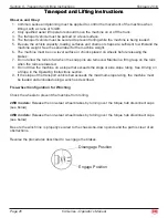
Страница 24: ...aerial work site is unsafe and dangerous Only trained and authorized personnel should be permitted to operate a machine If more than one operator is expected to use a machine at different times in th...

Страница 25: ...h the engine and rabbit icon to extinguish the indicator light Operation from Platform Turn the key switch to platform control Turn the ground red Emergency Stop button clockwise to the on position Pu...

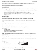
Страница 26: ...ratings for the machine and determine the slope grade Maximum forward slope rating stowed position 40 Maximum side slope rating stowed position 10 Note Slope rating is subject to ground conditions an...

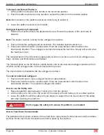
Страница 27: ...all outriggers are down All drive and lift functions are disabled The indicator lights on the lift function enable button and on the individual outrigger buttons will turn off when all the outriggers...

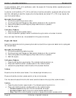
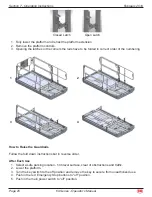
Страница 28: ...ded in correct order of the numbering 1 2 3 4 How to Raise the Guardrails Follow the fold down instructions but in reverse order After Each Use Select a safe parking location firm level surface clear...

Страница 29: ...removed Maintain a firm grasp on the rails when the rails are lowered Do not drive the machine on a slope that exceeds the slope or side slope rating See Driving on a Slope in the Operating Instructi...

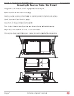
Страница 30: ...ecure the extension deck s Use the tie down points on the chassis for anchoring down to the transport surface Use a minimum of four chains or straps Use chains or straps of ample load capacity Turn th...

Страница 31: ...or the machine weight Lifting Instructions Fully lower the platform Be sure the extension decks controls and covers are secure Remove all loose items on the machine Determine the center of gravity of...

Страница 32: ...ebruary 2019 RT Machine Decal Locations 42528 1 2 3 4 5 6 7 8 9 10 11 12 13 14 15 17 16 9 18 21 19 20 16 3 23 6 1 2 1 7 6 2 24 25 9 12 13 15 22 16 6 3 10 11 14 1 6 4 5 7 14 On Material Rack 23 Section...

Страница 33: ...1 91553 Qty 1 91975 Qty 2 9052 Qty 1 91973 Qty 4 90722 Qty 1 90725 Qty 2 91850 Qty 4 90751 Qty 1 94872 Qty 2 90721 Qty 1 6873 Qty 1 90732 Qty 1 90719 Qty 1 42528 Qty 1 3369RT Only 94857 Qty 4 4069RT...

Страница 34: ...Plug ANSI CSA 2 10 9052 Decal Main Lockout Switch 1 11 90751 Decal Power To Platform 1 12 90719 Decal MEC Oval 1 13 92416 Decal Website 1 14 91973 Decal Tie Down 4 15 94872 Decal Warning Sheet Materia...

Страница 35: ...e 32 69 Series Operator s Manual February 2019 Section 9 Decals ERT Machine Decal Locations 42528 10 8 14 1 1 5 7 12 12 9 4 6 22 23 2 3 3 3 3 11 11 13 13 15 16 17 18 21 19 19 20 Second decal inside ho...

Страница 36: ...90722 Qty 1 90725 Qty 2 91850 Qty 4 90751 Qty 1 94872 Qty 2 90721 Qty 1 6873 Qty 1 90732 Qty 1 90719 Qty 1 42528 Qty 1 3369ERT Only 94868 Qty 2 4069ERT Only 94870 Qty 2 3369ERT Only 94856 Qty 4 1 5 9...

Страница 37: ...ecal Power To Platform 1 9 90719 Decal MEC Oval 1 10 92416 Decal Website 1 11 91973 Decal Tie Down 4 12 94872 Decal Warning Sheet Material Rack 300 LBS 2 13 94868 Decal 3369 Capacity 9 25 in 2 75 in 3...

Страница 38: ...ave a Purchase Order Number Fed Ex shipments require Fed Ex account number Part Number Description Quantity Price All back ordered parts will be shipped when available via the same ship method as orig...

Страница 39: ...on MEC Aerial Platform Sales Corp s then current flat rate provided the defective part in question is shipped prepaid to MEC Aerial Platform Sales Corp and is found upon inspection by MEC Aerial Plat...

Страница 40: ...1401 S Madera Avenue Kerman CA 93630 USA Toll Free 1 877 632 5438 Phone 1 559 842 1500 Fax 1 559 842 1520 info MECawp com www MECawp com MEC Aerial Work Platforms...

Отзывы: