DC20D MK2 GENSET CONTROLLER USER MANUAL
7
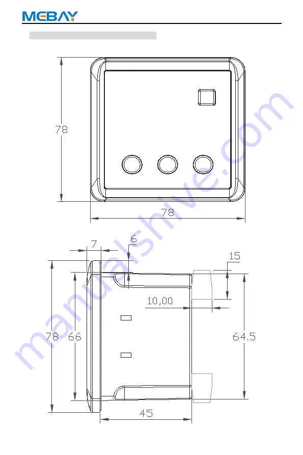
6. Overall Dimension and Wiring Diagram
Overall Dimension:
Страница 1: ...DC20D MK2 GENSET CONTROLLER USER MANUAL...
Страница 2: ...t fault delay function 3 V1 2 2020 05 01 Add RS485 communication baud rate and CRC check bit setting 4 V1 3 2021 02 01 Name of unified input and output port 5 V1 4 2021 06 01 Fix known errors in wirin...
Страница 3: ...ise it may cause the equipment not to work correctly Be care It is indicated that potential hazards can damage equipment without proper precautions Warning It is indicated if appropriate preventive me...
Страница 4: ...mage to related equipment 5 The engine must have an overspeed protection device independent of the controller system to avoid casualties or other damage caused by engine out of control 6 After the ins...
Страница 5: ...and operation instruction 12 10 Warnings and Shutdown Alarms 14 11 Parameters setting 18 12 Fault finding 23 Notes 1 All rights reserved No part of this duplication may be reproduced in any material...
Страница 6: ...uter 5 Units LED tube Display LED and Fault Alarm Code Indication Totally 4 relay s output among which 2 relay output can be self configurable each relay can be set as max 6 functions It has two senso...
Страница 7: ...Frequency 30 9999Hz MAX Accumulating Time 99999 9Hours Min Store time 6min Fuel Relay Output Max 5 Amp DC VE Supply voltage Start Relay Output Max 5 Amp DC VE Supply voltage AUX OUTPUT 1 Max 2 5 Amp...
Страница 8: ...DC20D MK2 GENSET CONTROLLER USER MANUAL 7 6 Overall Dimension and Wiring Diagram Overall Dimension...
Страница 9: ...Charging excitation output VE output Max 0 9 Amp 1 0mm2 8 Aux Input 1 Switch input Connect to the negative side of the active circuit 1 0mm2 9 Generator Voltage L Connect to generator set output L li...
Страница 10: ...PUT 1 GEN CURRENT GEN VOLTS SWITCH FUSE 10 A BATTERY FUEL CRANK AUX OUTPUT 2 ALT BATTERY NEGATIVE MUST BE GROUNDED AUX INPUT 2 AUX INPUT 3 P1 P2 S1 S2 L N RS485 MPU FUSE 2A TO LOAD Note Please don t m...
Страница 11: ...nected to battery positive and negative and the wire size must not be less than 2 5mm2 NOTE In case of floating charger connect charger output to battery positive and negative directly then connect ba...
Страница 12: ...in Function Stop Reset Revert Can stop generator under manual auto mode Can reset shutdown alarm During stop procession pressing this key again can stop generator immediately Pressing this key can can...
Страница 13: ...successful pressing the automatic key can be converted into an automatic file The specific working time is as follows 0RPM Idle Rated speed Pre heat delay 5S Long est pre oil supply delay 0S Start Cr...
Страница 14: ...ssful and the motor relay is closed Note 2 Within the safety delay only respond to emergency stop over speed over frequency over voltage Speed signal lost low fuel level warning other alarms are not r...
Страница 15: ...Under battery voltage warning Then start warning delay and the duration Normal alarm delay have not returned to normal the warning of Under battery voltage warning is reported Warning lights will lig...
Страница 16: ...rned to normal the alarm of over speed is reported Alarm lights will light up Generators will stop displays ALA 02 on the led screen Under speed alarm When the controller detects that the engine speed...
Страница 17: ...ture Switch is reported Alarm lights will light up Generators will stop displays ALA 08 on the led screen Low coolant level switch alarm When the controller detects that the AUX INPUT Low water level...
Страница 18: ...Phase current over load alarm Then start alarm delay and the duration Normal alarm delay have not returned to normal the alarm of over current is reported Alarm lights will light up Generators will st...
Страница 19: ...e 5 6000A 5A 500A 5A Used for setting genset CT primary current secondary rated current 5A 1 Flywheel teeth 0 300 0 If the setting is 0 RPM sensor Disabled then RPM is resulted by Hz 2 AUX INPUT 1 Fun...
Страница 20: ...40 120 11 Coolant temperature sensor Datcon High 12 Coolant temperature sensor 3015238 13 Coolant temperature sensor MEBAY Mier 14 Coolant temperature sensor User defined PC to configure Choose progra...
Страница 21: ...e 5 RPM Freq Oil Pressure Either of the conditions can be acceptable as crank condition But all of them should be meet together to regard as stop condition 13 RPM disconnect 350 999RPM 380RPM When the...
Страница 22: ...s T t IA IT 1 2 28 Oil pressure delay 0 3s 1s When the crank condition contains oil pressure if the oil pressure is higher than the preset value and continue for few seconds then it is regarded as cra...
Страница 23: ...r voltage alarms If the value is set as 500 then the alarm is disabled 37 Under voltage alarm 50 380V 100V When the voltage is lower than the value and comes into under voltage delay but still lower n...
Страница 24: ...ed alarm ALA 14 Coolant temperature sensor disconnected alarm ALA 03 Under speed alarm ALA 15 Over frequency alarm ALA 04 Low oil pressure alarm sensor ALA 16 Under frequency alarm ALA 05 Low oil pres...
Страница 25: ...s normal Shutdown Alarm in running Check related switch and its connections according to the information on LED Check AUX INPUT Fail to start Check fuel return circuit and wiring Check start battery C...