USB-4301 User's Guide
Functional Details
19
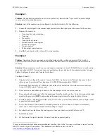
Example 1
Problem
: The application generates an active low pulse every time a button
1
is pressed.
You need a simple
event counter to count button presses.
Solution
: Any of the counters can be configured to do this fairly easily. Do the following:
1.
Connect the input signal to the counter input pin, and select that input pin as the source for the counter.
2.
Program the counter to:
o
Count negative edge transitions
o
Count up
o
No recycle
o
Count in binary mode
o
Reload from the Load register
o
Disable special gate
o
No gate control
o
Make output control inactive
3.
Load the Load register with a value of 0 to start counting.
Example 2
Problem
: An external device generates an active high signal while a switch is depressed. The switch is
depressed for at most one second. You need to measure the time the switch is depressed with microsecond
accuracy.
Solution
: Microsecond accuracy for one second requires counting to at most 1,000,000. However, each counter
can count only to 65,535. You can use some counter features to
cascade
two of the counters in order to count
higher. Configure Counter 1 and Counter 2 as follows:
Configure Counter 1:
1.
Using
Insta
Cal, configure the counter 1 source for 1 MHz. As shown in
the "
Internal frequency values
"
table on page 16, an internal base frequency of 1.0000 MHz corresponds to
FREQ1
.
The internal base frequency of 1 MHz provides an ideal way to measure time to the microsecond, since
1 count at 1 MHz equals 1 microsecond.
2.
The counter can count either up or down, so for this example set the counter to count up.
3.
The counter should count only while the input signal from the switch is active. To do this, connect the input
signal to the gate 1 pin (
GAT1
), and configure the counter gate control for active high level Gate
n
.
4.
Load the Counter 1 Load Register with a value of zero, since you want the counter to reach as high a count
as possible before reaching TC.
5.
To cascade Counter 1 with Counter 2, turn Recycle mode
on
. This is done so Counter 1 continuously
counts to TC, then wraps around and starts counting at 0 again.
6.
Set reload to always load from the Load register, since you want to restart at 0 after every TC.
7.
Enable binary mode.
8.
Set the Counter 1output to inactive; Counter 1 requires no special gating.
1
For more information about debouncing mechanical switches, refer to the "
Low pass to de-bounce inputs
" section
in MCC's
Guide to Signal Connections
. This document is available on our web site at
Содержание USB-4301
Страница 1: ......


