Measurement Computing USB-1608GX-AO Скачать руководство пользователя страница 20

USB-1608GX-2AO User's Guide 

Specifications 

20 

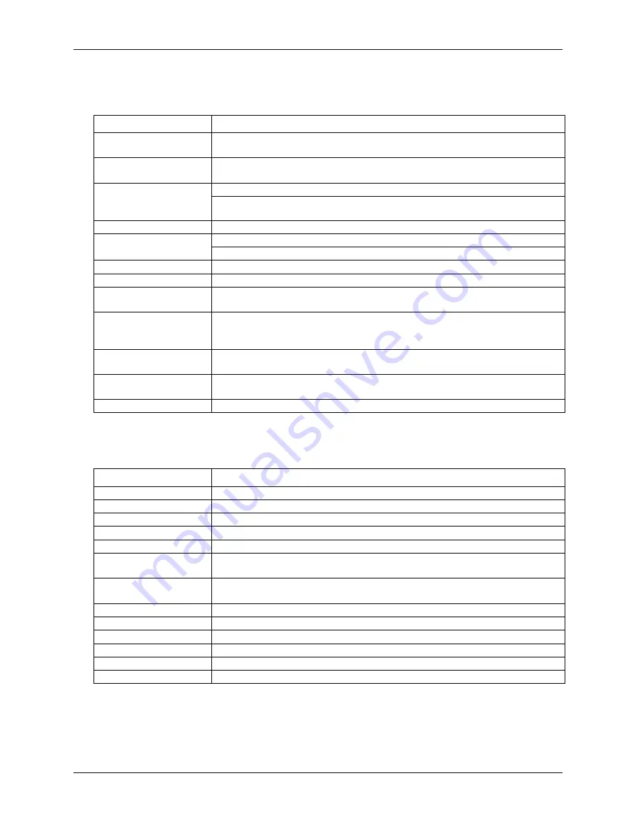
External clock input/output 

Table 12. External clock I/O specifications 

Parameter 

Specification 

Terminal names 

AICKI, AICKO 

AOCKI, AOCKO 

Terminal types 

AxCKI:  Input, active on rising edge 

AxCKO:  Output, power on default is 0 V, active on rising edge 

Terminal descriptions 

AxCKI:  Receives sampling clock from external source  
AxCKO:  Outputs the internal D/A or A/D sampling clock, or the pulse generated from 

AxCKI when in external clock mode. 

Input clock rate 

500 kHz max 

Clock pulse width 

AxCKI:  400 ns min 
AxCKO:  400 ns min 

Input type 

Schmitt trigger, 33 

Ω series resistor, 47


kΩ pull

-down to ground 

Schmitt trigger hysteresis 

0.4 V to 1.2 V 

Input high voltage 

2.2 V min 

5.5 V absolute max 

Input low voltage 

1.5 V max 

–0.5 V absolute min 

0 V recommended min 

Output high voltage  

4.4 V min (IOH = –50 µA) 

3.76 V min (IOH = –2.5 mA) 

Output low voltage  

0.1 V max (IOL = 50 µA) 

0.44 V max (IOL = 2.5 mA) 

Output current 

±2.5 mA max  

Counter 

Table 13. Counter specifications 

Parameter 

Specification 

Terminal names 

CTR0, CTR1 

Number of channels 

2 channels 

Resolution 

32-bit 

Counter type 

Event counter 

Input type 

Schmitt trigger, 33 

Ω series resistor, 47


kΩ pull

-down to ground 

Input source 

CTR0 (pin 52) 

CTR1 (pin 51) 

Counter read/writes rates 

(software paced) 

33 to 8000 reads/writes per second typ, system dependent 

Input high voltage  

2.2 V min, 5.5 V max 

Input low voltage 

1.5 V max, –0.5 V min 

Schmitt trigger hysteresis 

0.4 V min, 1.2 V max 

Input frequency 

20 MHz, max 

High pulse width 

25 ns, min 

Low pulse width 

25 ns, min 

Содержание USB-1608GX-AO

Страница 1: ...USB 1608GX 2AO Multifunction DAQ Device User s Guide January 2019 Rev 2 Measurement Computing...

Страница 2: ...any form by any means electronic mechanical by photocopying recording or otherwise without the prior written permission of Measurement Computing Corporation Notice Measurement Computing Corporation d...

Страница 3: ...apter 3 Functional Details 8 Analog input modes 8 Software paced 8 Hardware paced 8 Burst mode 8 External components 9 USB connector 9 LEDs 9 Screw terminals 9 Signal connections 11 Analog input 11 An...

Страница 4: ...2AO User s Guide 4 Counter 20 Timer 21 Memory 21 Power 21 USB 21 Environmental 22 Mechanical 22 Screw terminal connector 22 Differential mode pinout 22 Single ended mode pinout 23 EU Declaration of Co...

Страница 5: ...e names of objects on a screen such as buttons text boxes and check boxes italic text Italic text is used for the names of manuals and help topic titles and to emphasize a word or phrase Where to find...

Страница 6: ...terminals for field wiring connections The USB 1608GX 2AO is powered by the 5 volt USB supply from your computer no external power is required A USB cable is shipped with the device The USB 1608GX 2A...

Страница 7: ...he device The dialog closes after the device is installed A green Status LED indicates the device status When the LED is on the device is powered and ready for operation When the LED is off the device...

Страница 8: ...to the computer memory buffer You start a continuous scan with either a software command or with an external hardware trigger event The maximum sampling rate in hardware paced mode from one to 16 cha...

Страница 9: ...ter The Activity LED blinks when data is transferred and is off otherwise Figure 3 shows the location of each LED Screw terminals The screw terminals provide the following connections 16 SE CH0 to CH1...

Страница 10: ...USB 1608GX 2AO User s Guide Functional Details 10 Figure 4 SE mode pinout Figure 5 DIFF mode pinout...

Страница 11: ...voltage source When connecting DIFF voltage inputs to a floating voltage source make sure the DIFF input channel has a DC return path to ground To create this path connect a resistor from each low cha...

Страница 12: ...of 500 kS s The output range is fixed at 10 V The outputs default to 0 V when the host computer is shut down or suspended or when a reset command is issued to the device External clock I O The device...

Страница 13: ...pull up or pull down The jumper is configured by default for pull down Figure 8 shows the location of the jumper on the board Figure 8 W1 jumper location Figure 9 shows the jumper configured for pull...

Страница 14: ...z The timer output parameters are software selectable Figure 10 shows the timer output schematic Figure 10 Timer output schematic Power output The 5V terminal can output up to 10 mA maximum You can us...

Страница 15: ...USB 1608GX 2AO User s Guide Functional Details 15 Mechanical drawings Figure 11 USB 1608GX 2AO circuit board top and enclosure dimensions...

Страница 16: ...signal 3 dB 870 kHz Input capacitance 60 pf Max working voltage signal common mode 10V range 10 2 V max relative to AGND 5V range 10 2 V max relative to AGND 2V range 9 5 V max relative to AGND 1V ra...

Страница 17: ...connected to AGND at the input terminal block and 32 000 samples are acquired at the maximum rate available at each setting Table 3 Noise performance specifications Range Counts LSBrms 10 V 6 0 91 5 V...

Страница 18: ...urce TRIG see External trigger on page 19 Sample clock source Internal D A clock or external D A clock AOCKI pin Output update rate 500 kHz number of channels in scan Settling time To rated accuracy 1...

Страница 19: ...ion The port has 47 k resistors configurable as pull ups or pull downs default via internal jumper W1 Digital I O transfer rate system paced 33 to 8000 port reads writes or single bit reads writes per...

Страница 20: ...is 0 4 V to 1 2 V Input high voltage 2 2 V min 5 5 V absolute max Input low voltage 1 5 V max 0 5 V absolute min 0 V recommended min Output high voltage 4 4 V min IOH 50 A 3 76 V min IOH 2 5 mA Output...

Страница 21: ...2 kS analog output Non volatile memory 32 KB 28 KB firmware storage 4 KB calibration user data Power Table 16 Power specifications Parameter Condition Specification Supply current Note 3 Quiescent cu...

Страница 22: ...L AI channel 6 LO 5 CH1L AI channel 1 LO 32 CH6H AI channel 6 HI 6 AGND Analog ground 33 AGND Analog ground 7 CH2H AI channel 2 HI 34 CH5L AI channel 5 LO 8 CH2L AI channel 2 LO 35 CH5H AI channel 5 H...

Страница 23: ...I channel 12 11 CH11 AI channel 11 38 CH4 AI channel 4 12 AGND Analog ground 39 AGND Analog ground 13 AOUT0 AO channel 0 40 AGND Analog ground 14 AGND Analog ground 41 AGND Analog ground 15 AOUT1 AO c...

Страница 24: ...European Directives Electromagnetic Compatibility EMC Directive 2014 30 EU Low Voltage Directive 2014 35 EU RoHS Directive 2011 65 EU Conformity is assessed in accordance to the following standards E...

Страница 25: ...ion NI Hungary Kft 10 Commerce Way H 4031 Debrecen H tar t 1 A Hungary Norton Massachusetts 02766 Phone 36 52 515400 508 946 5100 Fax 36 52 515414 Fax 508 946 9500 http hungary ni com debrecen E mail...

Отзывы: