USB-1608FS-Plus User's Guide
Functional Details
16
Mechanical drawings
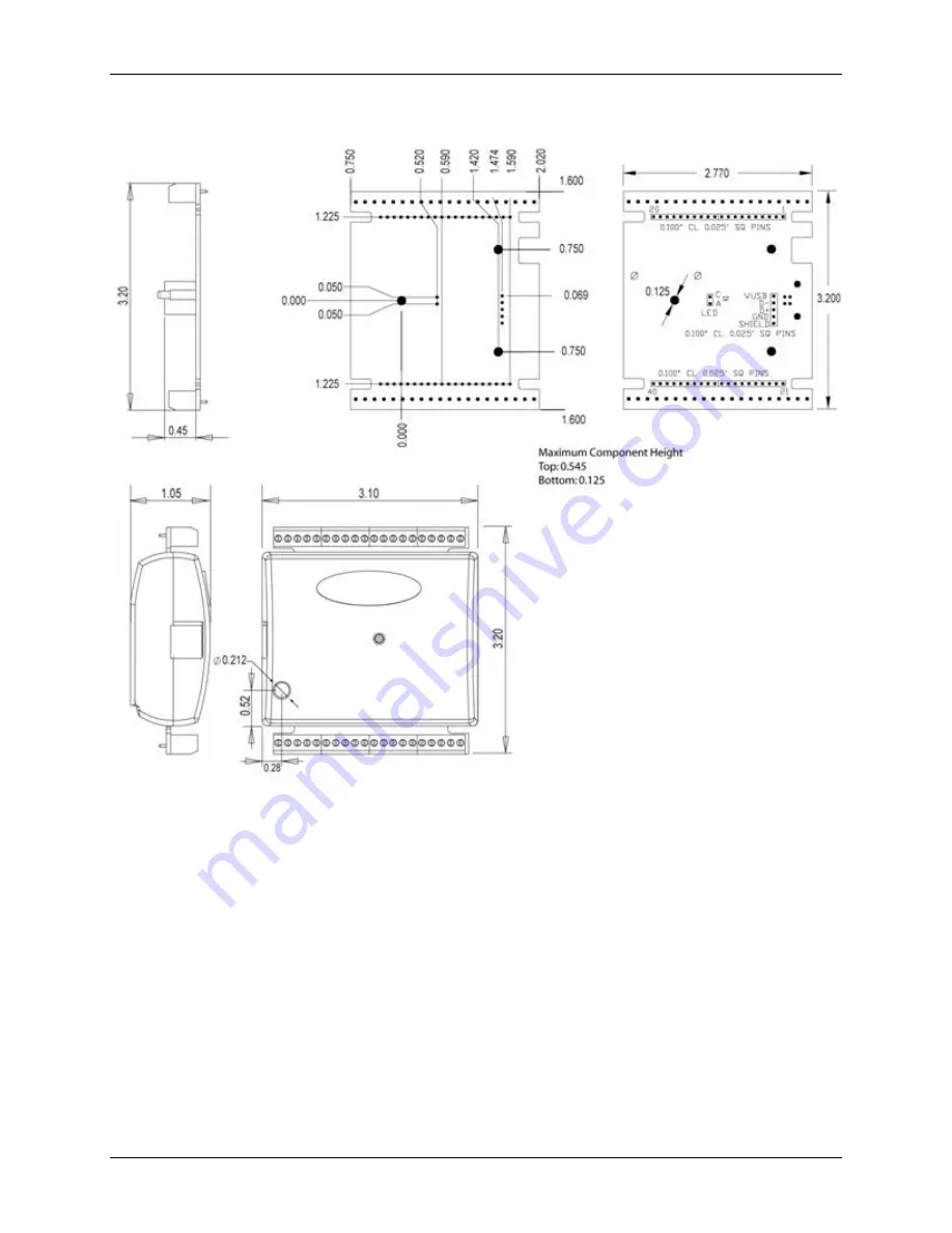
Figure 11. USB-1608FS-Plus circuit board (top) and enclosure dimensions
Страница 1: ...USB 1608FS Plus Analog Input and Digital I O Document Revision 5A November 2014 Copyright 2014 User s Guide...
Страница 2: ...ed in any form by any means electronic mechanical by photocopying recording or otherwise without the prior written permission of Measurement Computing Corporation Notice Measurement Computing Corporat...
Страница 3: ...7 Calibrating the hardware 8 Chapter 3 Functional Details 9 Analog input modes 9 Software paced 9 Hardware paced 9 BURSTIO 9 External components 10 USB connector 10 LED 10 Screw terminals 10 Signal c...
Страница 4: ...s User s Guide 4 External clock input output 19 Counter section 20 Memory 20 Microcontroller 20 Power 21 General 21 Environmental 21 Mechanical 21 Screw terminal connector and pinout 22 Declaration of...
Страница 5: ...names of objects on a screen such as buttons text boxes and check boxes italic text Italic text is used for the names of manuals and help topic titles and to emphasize a word or phrase Where to find...
Страница 6: ...One external digital trigger input Bidirectional external clock for synchronous operation with more than one device Screw terminals for field wiring connections The device is powered by the 5V USB su...
Страница 7: ...missing or damaged Installing the software Refer to the MCC DAQ Quick Start for instructions on installing the software on the MCC DAQ CD Refer to the device product page on the Measurement Computing...
Страница 8: ...ble from the computer and then reconnect it This should restore communication and the LED should turn on Calibrating the hardware The Measurement Computing Manufacturing Test department performs the i...
Страница 9: ...lock source The maximum sampling rate is an aggregate rate The total sample rate using hardware paced mode is 400 kS s divided by the number of channels with a maximum rate of 100 kS s for any channel...
Страница 10: ...tatus it cannot be disabled LED behavior LED state Indication On steady green The device is connected to a computer or external USB hub Blinks once A USB command is received Blinks continuously An ana...
Страница 11: ...ond wire to AGND The input voltage ranges are 10 V 5 V 2 0 V 1 0 V For more information on analog signal connections For more information on single ended inputs refer to the Guide to Signal Connection...
Страница 12: ...k resistor default You can change the pull up down configuration using the internal jumper labeled DIO You must remove the device housing to access the jumper on the circuit board To set the jumper fo...
Страница 13: ...nd AGND terminals provide a common ground for all analog channels The digital ground GND terminals provide a common ground for the digital trigger counter and sync channels and the power terminal Powe...
Страница 14: ...t mid scale Ideally a zero volt input should produce an output code of 32 768 Any deviation from this is an offset error Figure 8 shows the transfer function with an offset error The typical offset er...
Страница 15: ...standpoint than are values near mid scale which see little or no voltage error Combining these two error sources in Figure 10 we have a plot of the error band at full scale 10 V This plot is a graphi...
Страница 16: ...USB 1608FS Plus User s Guide Functional Details 16 Mechanical drawings Figure 11 USB 1608FS Plus circuit board top and enclosure dimensions...
Страница 17: ...V 5 V 2 V 1 V Sampling rate Hardware paced 0 01 S s to 100 kS s software selectable Throughput Software paced 500 S s all channels Hardware paced Note 1 400 kS s of channels max 100 kS s max for any...
Страница 18: ...are gathered at the maximum specified sampling rate of 100 kS s Digital input output Table 5 Digital I O specifications Parameter Specification Digital type 5V TTL Number of I O 8 DIO0 through DIO7 Co...
Страница 19: ...limit 0 5 V absolute min 0 V recommended min External clock input output Table 7 External clock I O specifications Parameter Condition Specification Pin name SYNC Pin type Bidirectional Direction sof...
Страница 20: ...typ 1 9 V min 3 1V max Input high voltage limit 5 5 V absolute max Input low voltage threshold 1 42 V typ 1 0 V min 2 0 V max Input low voltage limit 0 5 V absolute min 0 V recommended min Input freq...
Страница 21: ...tery powered root port hubs provide 100 mA or 500 mA depending upon the manufacturer A laptop PC that is not connected to an external power adapter is an example of a battery powered root port hub If...
Страница 22: ...WG to 30 AWG Table 16 Connector pinout Pin Signal Name Pin Signal Name 1 CH0 IN 21 DIO0 2 AGND 22 GND 3 CH1 IN 23 DIO1 4 AGND 24 GND 5 CH2 IN 25 DIO2 6 AGND 26 GND 7 CH3 IN 27 DIO3 8 AGND 28 GND 9 CH4...
Страница 23: ...ing conditions must be met The host computer peripheral equipment power sources and expansion hardware must be CE compliant All I O cables must be shielded with the shields connected to ground I O cab...
Страница 24: ...ion 10 Commerce Way Norton Massachusetts 02766 508 946 5100 Fax 508 946 9500 E mail info mccdaq com www mccdaq com NI Hungary Kft H 4031 Debrecen H tar t 1 A Hungary Phone 36 52 515400 Fax 36 52 51541...