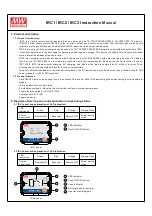
Mean Well IRC1 Скачать руководство пользователя страница 5

Model No : IRC3

Inverter Remote Controller

SOLAR CHARGE

Green
Orange
Red
Orange
Flash

ON
OFF
Abnormal
Power
Saving

:
:
:
:

AC

CHARGE

AC IN

BY PASS

INVERTER

100%

100%

BATTERY

0%

0%

LOAD

PUSH

ON / OFF

4

c.Screw set (M4 combination of screw &  nuts x 2 sets).

d.User's manual

1.

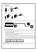
3.2 Installation method:

(1)Mount on top of a vertical surface

3.3 Cable connection:

3.4 Description of available functions:

3.4.1 Remotely control inverter ON/OFF:

3.4.2 Remotely enable or disable the power saving mode:

Please use the provided cable when connecting the controller device to the jack found on the front panel of the inverter. Refer to

the diagram below:

M4

M3

IRC1/2/3 can be used to remotely control inverter ON/OFF and enable or disable the power saving mode. After attaching the

After pushing the ON/OFF setting button, the inverter will immediately shut down. The load indicator will also reflect this

This controller offers flexible adjustment of the standby mode, enable or disable. The operating sequence is as follows, press

and hold on to the push ON/OFF button for about 3 seconds and the LED indicator will start flashing orange. Enter setting

mode after letting go of the push ON/OFF button. Power saving mode can be enable or disable by pressing the push ON/OFF

button. Check for setting status by inspection LED indication (refer to the chart below). After making your selection, hold on

to the push ON/OFF button for 5 seconds and the LED indicator will flash orange, let go of the push ON/OFF button and the

change in status. To restart the inverter, press the setting button again.

RJ11~RJ11 cable, all the LEDs on the device panel will light up, after waiting for about 5 seconds then the control process can

begin. No external power source is required for the controller.

(2)Mount inside system panel

If the inverter goes into protection due to abnormal operating condition and cannot be restarted using the controller unit, please go on

site to correct inverter failure condition and then resume remote operation.

4.Cautionary notes

inverter will automatically restart to complete the setting sequence.

LED indicator

Green

Red

Status description Enable power saving mode Disable power saving mode

Содержание IRC1

Страница 1: ...IRC1 IRC2 IRC3 Instruction Manual ...

Страница 2: ...lly understand the solar inverter s current state To satisfy different demands for remote control distances the RC device can be matched with 3 types of cable length 10ft cable standard or 25ft 50ft optional Push ON OFF button can be used to turn the output of the inverter ON or OFF and setting the power saving function enable or disable LED indications for inverter status 2 installation methods M...

Страница 3: ...FF AC charger ON OFF AC utility normal AC utility providing load E F G D H A A B C D E F G H I I I I I I B C 2 2 1 Explanation of abnormal conditions Abnormal output voltage level Output short protection Battery input UVP OVP Battery fail protection Battery aged Fan lock protection Load indicator Load indicator Load indicator Load indicator Load indicator Load indicator Load indicator Load indicat...

Страница 4: ... Battery fail protection Battery aged Fan lock protection Load indicator Load indicator Load indicator Load indicator Load indicator Load indicator Load indicator Load indicator Load indicator Load indicator Status description Status description Status description Status description Status description Status description Status description Status description Status description Status description Ou...

Страница 5: ...as follows press and hold on to the push ON OFF button for about 3 seconds and the LED indicator will start flashing orange Enter setting mode after letting go of the push ON OFF button Power saving mode can be enable or disable by pressing the push ON OFF button Check for setting status by inspection LED indication refer to the chart below After making your selection hold on to the push ON OFF bu...

Страница 6: ...to void may be required to take adequate measures product warranty power saving mode Inverter is abnormal Check inverter status and clear RC ON OFF not operational abnormal condition Operational error Please refer to 3 4 2 for more details Can not set Failure condition Probable cause Possible solution Improper wiring connection Please use the provided cable accessory Do not use ordinary telephone ...

Страница 7: ...F TS200 112F TS400 224B TS 3000 112F TS200 224B TN 3000 124F TN 1500 248B IRC3 10ft Cable IPS 1000S 12V 230V ECO MODE IPS 1200S 24V 230V ECO MODE IPS 4000S 12V 230V ECO MODE IPS 800U 12V 230V 3IPS030024 3IPS40024 3IPS050012 SINUS 10000PRO 12V SINUS 850PRO 12V SINUSPRO 1000E 3IPS100024 3IPS500012 3IPS500024 3IPS651012 3IPS651024 3IPS912246 3IPS912249 RED 16 24 12V 16A RED 6 24 12V 6A DC 120 12 24V ...

Отзывы: