


Technical
Manual
Room
Temperature
Controller
SCN
‐
RT1
MDT technologies GmbH •
51766 Engelskirchen • Papiermühle 1
Tel.: +49-2263-880 • Fax: +49-2263-4588 • [email protected] • www.mdt.de
42
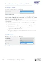
The
dynamic
range
for
an
additional
level
is
shown
at
the
following
chart
(the
setting
options
are
shown,
when
an
additional
level
is
activated):
ETS
‐
text
Dynamic
range
[default
value]
comment
Direction
of
controller
normal
inverted
indicates
the
controlling
behavior
at
rising
temperature
(4.5.5)
Control
value
2
‐
Step
control
(switching)
PI
control
switching
(PWM)
Setting
of
the
used
control
value
Distance
(in
K)
1,0K
–
10,0K
[2,0K]
Distance
between
the
setpoints
of
the
normal
controlling
and
the
setpoint
for
the
additional
level
Chart
40:
Additional
level
An
additional
level
can
only
be
chosen
for
heating.
The
direction
of
the
controller
can
be
chosen
for
the
additional
level,
too.
The
control
value
can
be
chosen
as
PI
‐
control
switching
(PWM)
or
2
‐
Step
control.
So
the
communication
object
for
the
additional
level
has
always
the
size
of
1
Bit.
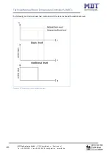
The
distance
in
K
describes
the
setpoint
of
the
additional
level.
The
adjusted
distance
is
deducted
from
the
setpoint
of
the
basic
level;
the
resulting
value
is
the
setpoint
for
the
additional
level.
Example:
The
controller
has
the
operating
mode
comfort,
with
the
basic
comfort
setpoint
of
21°C.
The
distance
is
adjusted
as
2,0K.
So
the
setpoint
for
the
additional
level
is
21°C
‐
2,0K=19,0°C.
An
additional
level
can
be
used
at
carry
systems
to
reduce
the
warm
up
time.
For
example
can
a
radiator
be
used
as
additional
level
for
reducing
the
war
up
time
of
an
underfloor
heating.
The
following
chart
shows
the
relevant
communication
object:
Number
Name
Length
Usage
9
Control
value
additional
heating
1
Bit
control
value
for
the
additional
level
Chart
41:
Communication
object
additional
level