


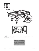


Go back and make sure that all connections are tight.
X 4
X 18
X 1
1
24
30
FIG. 11
24
FIG. 11B
FIG. 11A
10
30
11
1
1
1
12
12
11
15
10
9
1
9
15
P1
FIG.11
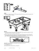
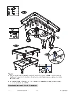
21. Place the Mainframe (#1) on the top of the pre-assembled Lower Table
(See FIG. 10).
Underneath the
Mainframe (#1), assemble the Mainframe (#1) to the Side & End Top Boards using eighteen Bolts (#30).
See FIG.11 & 11A.
22. Attach the Adjustable "L" Bracket (#P1) to the backside of the Mainframe (#1) using two Screws (#24)
per “L” Brackets (#P1).
See FIG.11B.
www.themdsports.com
1439021
10
(Continued on the next page.)