background image

CSP

902RFM207E

1

ROTORCRAFT FLIGHT MANUAL

MD900 (902 Configuration with PW 207E)

Emergency and

Malfunction Procedures

FAA Approved

Reissue 2

Original

3

30

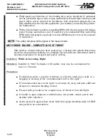
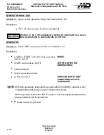
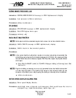
GENERATOR HIGH LOAD

Indications:

Upper yellow generator high load annunciator ON.

Procedures:

Turn off unnecessary electrical equipment.

Failure to turn off unnecessary electrical equipment may cause

the generator(s) to automatically go off line.

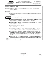
GENERATOR

Indications:

Yellow GEN annunciator ON and %LOAD is ``0''.

Procedures:

L GEN or R GEN (or both if dual generator
failure) switch

RESET

If GEN annunciator still ON

OFF FOR AFFECTED

GENERATOR(S)

Continue flight.

If both generators failed.

Power switch

ESNTL UNLESS FLIGHT

CONDITIONS DICTATE

OTHERWISE

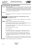
NOTE

:

With both generators failed and the power switch in the ESNTL position, a fully

charged battery will supply power for at least 30 minutes.

WIth the power switch in the ESNTL position, only that equipment powered by

the essential bus will be operational.

Land as soon as practical.

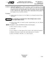
CAUTION

Содержание MD900 Explorer

Страница 1: ...08 E02686 Reissue 1 2 December 2008 E02686 Revision 1 21 July 2009 E02686 Reissue 2 6 November 2009 E02686 Reissue 2 EASA i CSP 902RFM207E 1 As of 28 September 2003 the EASA began approving FAA rotorcraft flight manuals Operators of MD900 series helicopters registered in a European Union member state are required to place this approval page after the cover page in their flight manual European Avia...

Страница 2: ...CSP 902RFM207E 1 ROTORCRAFT FLIGHT MANUAL MD900 902 Configuration with PW 207E EASA ii This page intentionally left blank ...

Страница 3: ...CSP 902RFM207E 1 Model MD900 902 Configuration with PW 207E F90 001 R O T O R C R A F T F L I G H T M A N U A L REGISTRATION NO _________________ SERIAL NO _________________ Cover ...

Страница 4: ......
Страница 5: ... THE FOLLOWING SECTIONS SECTION II LIMITATIONS SECTION III EMERGENCY PROCEDURES SECTION IV NORMAL PROCEDURES SECTION V PERFORMANCE DATA SECTION X OPTIONAL EQUIPMENT SECTION XI CATEGORY A OPERATIONS The helicopter must be operated in compliance with the operating limitations as set forth in section II of this manual and any additional limitations from Section X as a result of an installed optional ...

Страница 6: ... 2003 Revision 6 22 September 2003 Revision 7 13 January 2004 Revision 8 8 July 2005 Revision 9 21 August 2007 Revision 10 20 February 2008 Revision 11 11 April 2008 Reissue 1 2 December 2008 Revision 1 21 July 2009 Reissue 2 06 November 2009 Revision 1 03 February 2012 Revision 2 03 August 2012 Revision 3 10 January 2013 Revision 4 28 January 2014 Revision 5 30 September 2014 Approved By Manager ...

Страница 7: ...s a four digit approval number See MDHI web page http www mdhelicop ters com publications link for EASA approval number and instructions National Agency of Civil Aviation Brazil This Aircraft Flight Manual is approved by the FAA on behalf of the National Agency of Civil Aviation for Brazilian registered aircraft in accordance with the Regulamentos Brasileiros de Homologação Aeronáutica RBHA 21 Sec...

Страница 8: ...CSP 902RFM207E 1 ROTORCRAFT FLIGHT MANUAL MD900 902 Configuration with PW 207E Original F iv Reissue 2 This page intentionally left blank ...

Страница 9: ...resentation 1 3 1 5 Definition of Terms 1 3 1 6 Abbreviations 1 4 1 7 Multi Purpose Utility Operations 1 7 1 8 Technical Publications 1 7 1 9 Rotorcraft Certification 1 9 1 10 Pilot s Briefing 1 9 1 11 Dimensions 1 10 1 12 Conversion Charts 1 12 Section II Limitations 2 1 Flight Restrictions 2 1 2 2 Environmental Operating Conditions 2 2 2 3 Airspeed Limitations 2 4 2 4 Weight Limitations 2 6 2 5 ...

Страница 10: ...tdown Manual 3 14 3 8 Fire Emergencies 3 15 3 9 Flight Control Malfunctions 3 19 3 10 Pitot Static System Malfunction Single or Dual Pitot Tube Installation 3 26 3 11 Engine and Generator Malfunction Indications 3 27 3 12 Transmission Malfunction Indications 3 31 3 13 Fuel System Display Advisories 3 34 3 14 Caution and Warning Advisories 3 38 3 15 Other Malfunction Advisories 3 42 3 16 Vibrations...

Страница 11: ...art 5 3 5 4 Airspeed Calibration 5 5 5 5 Best Rate of Climb Speed 5 7 5 6 Rate of Climb and Descent OEI 5 9 5 7 Rate of Climb AEO 5 25 5 8 Hover Ceiling AEO 5 44 5 9 Hover Ceiling OEI 5 54 5 10 Height Velocity Diagram 5 57 5 11 Power Assurance Check Automatic 5 58 5 12 Power Assurance Check Manual 5 60 Section VI Weight and Balance Data 6 1 Weight and Balance Characteristics 6 1 6 2 Load Limits an...

Страница 12: ...1 Fuel System 7 31 7 12 Fire Extinguishing System 7 34 7 13 Electrical System 7 36 7 14 Environmental Control 7 39 7 15 Integrated Instrumentation Display System IIDS 7 41 7 16 IIDS Data Storage 7 49 7 17 Balance Monitoring System 7 52 7 18 IIDS Menu Structures 7 53 Section VIII Handling Servicing and Maintenance 8 1 Hoisting Lifting and Jacking 8 1 8 2 Towing and Moving 8 1 8 3 Parking and Storag...

Страница 13: ... 10 8 Operating Instructions Windscreen Wipers 10 21 10 9 Operating Instructions Supplemental Fuel System 10 25 10 10 Operating Instructions Rescue Hoist 10 35 10 11 Operating Instructions Removable CoPilot Controls 10 49 10 12 Operating Instructions Airframe Fuel Filter 10 55 10 13 Operating Instructions SX 16 Night Sun with Aft Mount 10 59 10 14 Operating Instructions RDR 1400C Weather Radar 10 ...

Страница 14: ... Takeoff Procedures 11 15 11 3 3 Landing Procedures Clear Airfield Heliport and Elevated Helipad 11 17 11 3 4 Confined Heliport Helipad Takeoff procedures 11 20 11 3 5 Takeoff Decision Point TDP 11 21 11 3 6 Rejected Takeoff Confined heliport 11 22 11 3 7 Continued Takeoff Confined Heliport 11 24 11 3 8 Short field Takeoff Procedures 11 26 11 3 9 Confined heliport and Balked landing Procedures 11 ...

Страница 15: ... pages Black and white reproductions of color pages are not considered to be FAA Approved REVISION NUMBER REMARKS Revision 5 Section V Paragraph 5 1 corrected the metric conversion of the maximum gross weight within the NOTE Paragraph 5 2 corrected the metric conversion in Table 5 1 and added Table 5 2 for noise characteristics of max gross weight of 6500 lb Section IX Paragraph 9 3 added Tables 9...

Страница 16: ...Reissue 2 Revision 4 F x Reissue 2 Revision 5 F xi Reissue 2 Revision 5 F xii Reissue 2 Revision 5 F xiii Reissue 2 Revision 4 F xiv Reissue 2 Revision 4 F xv Reissue 2 Revision 4 F xvi Reissue 2 Revision 5 F xvii Reissue 2 Revision 5 F xviii Reissue 2 Revision 5 F xix Reissue 2 Revision 5 F xx Reissue 2 Revision 5 F xxi Reissue 2 Revision 5 F xxii Reissue 2 Revision 5 F xxiii Reissue 2 Revision 5...

Страница 17: ...Reissue 2 Original 1 14 Reissue 2 Original 1 15 Reissue 2 Original 1 16 Reissue 2 Original 1 17 Reissue 2 Original 1 18 Reissue 2 Original 1 19 Reissue 2 Original 1 20 Reissue 2 Original II 2 i Reissue 2 Revision 4 2 ii Reissue 2 Revision 4 2 1 Reissue 2 Revision 4 2 2 Reissue 2 Revision 4 2 3 Reissue 2 Revision 4 2 4 Reissue 2 Revision 4 2 5 Reissue 2 Revision 4 2 6 Reissue 2 Revision 4 2 7 Reiss...

Страница 18: ... 3 2 Reissue 2 Original 3 3 Reissue 2 Original 3 4 Reissue 2 Original 3 5 Reissue 2 Original 3 6 Reissue 2 Original 3 7 Reissue 2 Original 3 8 Reissue 2 Original 3 9 Reissue 2 Original 3 10 Reissue 2 Original 3 11 Reissue 2 Original 3 12 Reissue 2 Original 3 13 Reissue 2 Original 3 14 Reissue 2 Original 3 15 Reissue 2 Original 3 16 Reissue 2 Original 3 17 Reissue 2 Revision 1 3 18 Reissue 2 Revisi...

Страница 19: ...ssue 2 Original 3 37 Reissue 2 Original 3 38 Reissue 2 Original 3 39 Reissue 2 Original 3 40 Reissue 2 Original 3 41 Reissue 2 Original 3 42 Reissue 2 Revision 2 3 43 Reissue 2 Original 3 44 Reissue 2 Original 3 45 Reissue 2 Original 3 46 Reissue 2 Original 3 47 Reissue 2 Original 3 48 Reissue 2 Original IV 4 i Reissue 2 Revision 4 4 ii Reissue 2 Original 4 1 Reissue 2 Original 4 2 Reissue 2 Origi...

Страница 20: ...nal 4 21 Reissue 2 Original 4 22 Reissue 2 Original 4 23 Reissue 2 Revision 1 4 24 Reissue 2 Original 4 25 Reissue 2 Original 4 26 Reissue 2 Original 4 27 Reissue 2 Revision 2 4 28 Reissue 2 Original 4 29 Reissue 2 Original 4 30 Reissue 2 Original 4 31 Reissue 2 Original 4 32 Reissue 2 Original 4 33 Reissue 2 Revision 4 4 34 Reissue 2 Revision 4 V 5 i Reissue 2 Revision 5 5 ii Reissue 2 Revision 5...

Страница 21: ... Revision 5 5 18 Reissue 2 Revision 5 5 19 Reissue 2 Revision 5 5 20 Reissue 2 Revision 5 5 21 Reissue 2 Revision 5 5 22 Reissue 2 Revision 5 5 23 Reissue 2 Revision 5 5 24 Reissue 2 Revision 5 5 25 Reissue 2 Revision 5 5 26 Reissue 2 Revision 5 5 27 Reissue 2 Revision 5 5 28 Reissue 2 Revision 5 5 29 Reissue 2 Revision 5 5 30 Reissue 2 Revision 5 5 31 Reissue 2 Revision 5 5 32 Reissue 2 Revision ...

Страница 22: ...2 Revision 5 5 52 Reissue 2 Revision 5 5 53 Reissue 2 Revision 5 5 54 Reissue 2 Revision 5 5 55 Reissue 2 Revision 5 5 56 Reissue 2 Revision 5 5 57 Reissue 2 Revision 5 5 58 Reissue 2 Revision 5 5 59 Reissue 2 Revision 5 5 60 Reissue 2 Revision 5 5 61 Reissue 2 Revision 5 5 62 Reissue 2 Revision 5 5 63 Reissue 2 Revision 5 5 64 Reissue 2 Revision 5 5 65 Reissue 2 Revision 5 5 66 Reissue 2 Revision...

Страница 23: ...inal 6 17 Reissue 2 Original 6 18 Reissue 2 Original 6 19 Reissue 2 Original 6 20 Reissue 2 Original 6 21 Reissue 2 Original 6 22 Reissue 2 Original VII 7 i Reissue 2 Original 7 ii Reissue 2 Original 7 iii Reissue 2 Original 7 iv Reissue 2 Original 7 1 Reissue 2 Original 7 2 Reissue 2 Original 7 3 Reissue 2 Original 7 4 Reissue 2 Original 7 5 Reissue 2 Original 7 6 Reissue 2 Original 7 7 Reissue 2...

Страница 24: ...sue 2 Original 7 25 Reissue 2 Original 7 26 Reissue 2 Original 7 27 Reissue 2 Original 7 28 Reissue 2 Original 7 29 Reissue 2 Original 7 30 Reissue 2 Original 7 31 Reissue 2 Original 7 32 Reissue 2 Original 7 33 Reissue 2 Original 7 34 Reissue 2 Original 7 35 Reissue 2 Original 7 36 Reissue 2 Original 7 37 Reissue 2 Original 7 38 Reissue 2 Original 7 39 Reissue 2 Original 7 40 Reissue 2 Original 7...

Страница 25: ...nal 7 58 Reissue 2 Original 7 59 Reissue 2 Original 7 60 Reissue 2 Original 7 61 Reissue 2 Original 7 62 Reissue 2 Original 7 63 Reissue 2 Original 7 64 Reissue 2 Original 7 65 Reissue 2 Original 7 66 Reissue 2 Original 7 67 Reissue 2 Original 7 68 Reissue 2 Original 7 69 Reissue 2 Original 7 70 Reissue 2 Original 7 71 Reissue 2 Original 7 72 Reissue 2 Original VIII 8 i Reissue 2 Original 8 ii Rei...

Страница 26: ... Original 8 18 Reissue 2 Original 8 19 Reissue 2 Original 8 20 Reissue 2 Original 8 21 Reissue 2 Original 8 22 Reissue 2 Original 8 23 Reissue 2 Original 8 24 Reissue 2 Revision 1 8 25 Reissue 2 Original 8 26 Reissue 2 Revision 1 8 27 Reissue 2 Original 8 28 Reissue 2 Original 8 29 Reissue 2 Revision 1 8 30 Reissue 2 Original 8 31 Reissue 2 Original 8 32 Reissue 2 Original 8 33 Reissue 2 Original ...

Страница 27: ... 2 Original IX 9 i Reissue 2 Revision 5 9 ii Reissue 2 Revision 5 9 1 Reissue 2 Original 9 2 Reissue 2 Original 9 3 Reissue 2 Original 9 4 Reissue 2 Original 9 5 Reissue 2 Original 9 6 Reissue 2 Original 9 7 Reissue 2 Original 9 8 Reissue 2 Original 9 9 Reissue 2 Original 9 10 Reissue 2 Original 9 11 Reissue 2 Original 9 12 Reissue 2 Original 9 13 Reissue 2 Original 9 14 Reissue 2 Original 9 15 Re...

Страница 28: ...10 iv Reissue 2 Original 10 1 Reissue 2 Original 10 2 Reissue 2 Original 10 3 Reissue 2 Original 10 4 Reissue 2 Original 10 5 Reissue 2 Original 10 6 Reissue 2 Original 10 7 Reissue 2 Original 10 8 Reissue 2 Original 10 9 Reissue 2 Original 10 10 Reissue 2 Original 10 11 Reissue 2 Original 10 12 Reissue 2 Original 10 13 Reissue 2 Original 10 14 Reissue 2 Original 10 15 Reissue 2 Original 10 16 Rei...

Страница 29: ...nal 10 34 Reissue 2 Original 10 35 Reissue 2 Revision 4 10 36 Reissue 2 Revision 4 10 37 Reissue 2 Original 10 38 Reissue 2 Original 10 39 Reissue 2 Revision 4 10 40 Reissue 2 Original 10 41 Reissue 2 Original 10 42 Reissue 2 Original 10 43 Reissue 2 Original 10 44 Reissue 2 Revision 4 10 45 Reissue 2 Original 10 46 Reissue 2 Original 10 47 Reissue 2 Original 10 48 Reissue 2 Original 10 49 Reissue...

Страница 30: ...riginal 10 68 Reissue 2 Original 10 69 Reissue 2 Original 10 70 Reissue 2 Original 10 71 Reissue 2 Original 10 72 Reissue 2 Original 10 73 Reissue 2 Original 10 74 Reissue 2 Original 10 75 Reissue 2 Original 10 76 Reissue 2 Original 10 77 Reissue 2 Original 10 78 Reissue 2 Original 10 79 Reissue 2 Original 10 80 Reissue 2 Original 10 81 Reissue 2 Original 10 82 Reissue 2 Original 10 83 Reissue 2 O...

Страница 31: ... Revision 3 11 2 Reissue 2 Revision 3 11 3 Reissue 2 Original 11 4 Reissue 2 Original 11 5 Reissue 2 Revision 4 11 6 Reissue 2 Original 11 7 Reissue 2 Original 11 8 Reissue 2 Original 11 9 Reissue 2 Revision 4 11 10 Reissue 2 Revision 4 11 11 Reissue 2 Revision 4 11 12 Reissue 2 Revision 4 11 13 Reissue 2 Revision 4 11 14 Reissue 2 Revision 4 11 15 Reissue 2 Revision 4 11 16 Reissue 2 Revision 4 1...

Страница 32: ...ion 4 11 29 Reissue 2 Revision 4 11 30 Reissue 2 Revision 4 11 31 Reissue 2 Revision 4 11 32 Reissue 2 Revision 4 11 33 Reissue 2 Revision 4 11 34 Reissue 2 Revision 4 11 35 Reissue 2 Revision 4 11 36 Reissue 2 Revision 4 11 37 Reissue 2 Revision 4 11 38 Reissue 2 Revision 4 11 39 Reissue 2 Revision 4 11 40 Reissue 2 Revision 4 11 41 Reissue 2 Revision 4 11 42 Reissue 2 Revision 4 11 43 Reissue 2 ...

Страница 33: ...ilot s Briefing 1 9 1 11 Dimensions 1 10 Figure 1 1 MD Explorer Rotorcraft Principal Dimensions 1 10 Figure 1 2 Interior Dimensions and Volumes 1 11 1 12 Conversion Charts 1 12 Figure 1 3 Speed MPH Knots KmH 1 12 Figure 1 4 Speed Knots Meters Second 1 13 Figure 1 5 Temperature Conversion Chart 1 14 Figure 1 6 Liquid Measure U S Gallons to Liters to Imperial Gallons 1 15 Figure 1 7 Linear Measure I...

Страница 34: ...ROTORCRAFT FLIGHT MANUAL MD900 902 Configuration with PW 207E CSP 902RFM207E 1 General Original 1 ii Reissue 2 PARAGRAPH PAGE This page intentionally left blank ...

Страница 35: ...ents Summary of Revisions and the List of Effective Pages By referring to the Log of Revisions By Date the pilot may review a chronological listing of changes to the Flight Manual Reading the Summary of Revisions will inform the pilot of what changes have been made by paragraph reference This Summary contains only the latest Flight Manual Change The List of Effective Pages allows the pilot quick r...

Страница 36: ...lance report and equipment list equipment both required and optional installed on the aircraft at the time of licensing SECTION VII SYSTEMS DESCRIPTION Offers a pilot oriented technical description of the operation of each system installed on the helicopter SECTION VIII AIRCRAFT HANDLING SERVICING MAINTENANCE The information contained in this section is extracted from the Handbook of Maintenance I...

Страница 37: ... on that page A hand points to changes in the contents of an illustration A WARNING brings to the pilot s immediate attention that equipment damage and or personal injury will occur if the instruction is disregarded placed after the instruction step A CAUTION alerts the individual that equipment damage may result if the procedural step is not followed to the letter placed after the instruction ste...

Страница 38: ...ual to or greater than Less than Equal to or less than A AC Air Conditioner AEO All Engines Operating A N Alphanumeric AGL Above Ground Level ALT Alternate Altitude AOG Aircraft On Ground APU Auxiliary Power Unit ASCM Aircraft Systems Condition Monitoring ATT Attitude B BAT Battery BIT Built In Test BL Butt Line BLD Bleed BMS Balance Monitoring System C CAB Cabin CAB HEAT Cabin Heat CC Cubic Centi...

Страница 39: ...er Unit H HAT Height Above Touchdown HD Density Altitude Hg Mercury HIRF High Intensity Radiated Field HP Pressure Altitude HSI Horizontal Situation Indicator Hot Section Inspection HVR Hover HYD Hydraulic I IAS Indicated Airspeed ICS Intercom System IFR Instrument Flight Rules IGE In Ground Effect IIDS Integrated Instrumentation Display System IMC Instrument Meteorological Conditions INST Instrum...

Страница 40: ...tor Speed O OAT Outside Air Temperature OEI One Engine Inoperative OGE Out of Ground Effect OVRD Override OVSP Overspeed P PLA Power Lever Angle PMA Permanent Magnet Alternator PNL Panel POSN Position PRI Primary Pt Pint PWC Pratt and Whitney Canada R R Right REL Release RET Retract R H Right Hand RTR Rotor S Sec Seconds SEL Sound Exposure Level SL Sea Level SLT Searchlight SSO Starts since overha...

Страница 41: ... ap proved for the MD EXPLORER may be installed and used 1 8 TECHNICAL PUBLICATIONS A file of technical publications is available to aid in obtaining maximum utilization of your rotorcraft Revisions and new issue publications are provided to continually update and expand existing data MDHI Publications Revisions and Reissues Changes in limitations procedures performance optional equipment etc re q...

Страница 42: ...in the page margin on the effected pages The following publications are available Rotorcraft Flight Manual RFM Rotorcraft Maintenance Manual RMM Servicing and Maintenance Instruments Electrical Avionics Component Maintenance Manual CMM Structural Repair Manual SRM Illustrated Parts Catalog IPC Service Information Bulletins and Letters New and revised publications are available through MDHS Subscri...

Страница 43: ... August 8 1996 The rotorcraft is certified by the Federal Aviation Administration under FAA Type Certificate Number H19NM The FAA model designation is MD900 The FAA ICAO aircraft type designator is EXPL The MD Helicopters Inc commercial designation is MD Explorer 1 10 PILOT S BRIEFING Prior to flight passengers should be briefed on the following Approach and depart the rotorcraft from the front in...

Страница 44: ...o Figure 1 1 and Figure 1 2 for exterior dimensions and interior volumes f92 002B 5 33 FT 5 0 9 17 FT STATIC GROUND LINE DESIGN GROSS WEIGHT 3 16 12 00 FT 10 92 FT 9 33 FT 7 33 FT 33 83 FT 1 62 M 5 92 FT 1 80 M 10 34 M 2 23 M 3 66 M 3 33 M 2 79 M 40 58 FT 12 37 m 34 08 FT 10 39 M Figure 1 1 MD Explorer Rotorcraft Principal Dimensions ...

Страница 45: ... General Original 1 11 Reissue 2 4 08 FT 1 2 M 4 16 FT 1 2 M WITH DOOR ON 4 33 FT 1 3 M WITH DOOR OFF ENTIRE AFT CABIN 172 5 FT3 4 9 M3 BAGGAGE COMPARTMENT 51 4 FT3 1 5 M3 4 75 FT 1 4 M 18 25 FT 5 5 M 12 9 FT 3 9 M 6 25 FT 1 9 M F90 003 Figure 1 2 Interior Dimensions and Volumes ...

Страница 46: ...0 80 60 40 20 0 180 160 140 120 100 80 60 40 20 0 200 180 160 140 120 100 80 60 40 20 0 220 240 260 280 300 320 MPH Km H KNOTS EXAMPLE CONVERT 100 KNOTS TO MPH AND TO KM HR ENTER CHART AT 100 KNOTS AND FOLLOW ARROW TO SLOPING LINE TO FIND MPH MOVE LEFT AND READ 115 MPH TO FIND KM HR MOVE RIGHT FROM THE SLOPING LINE AND READ 185 KM HR Figure 1 3 Speed MPH Knots KmH ...

Страница 47: ... 006 METERS SEC KNOTS CONVERT KNOTS TO METERS SEC KNOWN WIND SPEED 25 KT METHOD ENTER CHART AT 25 KT READ APPROXIMATELY 13 METERS SEC ACROSS ON METERS SEC SCALE METHOD MAY BE REVERSED TO FIND KNOTS WHEN METERS SEC ARE KNOWN EXAMPLE 0 5 10 15 20 25 30 35 40 45 50 0 5 10 15 20 25 Figure 1 4 Speed Knots Meters Second ...

Страница 48: ...T F TO C KNOWN TEMPERATURE 50 F METHOD ENTER AT 50 F READ 10 C ACROSS ON C SCALE METHOD MAY BE REVERSED TO FIND F WHEN C IS KNOWN ALTERNATE METHOD F 9 5 X C 32 C 5 9 F 32 TEMPERATURE EXAMPLE F C 140 120 100 80 60 40 20 0 20 40 60 60 40 20 0 20 40 60 80 f92 005 50 30 10 10 30 50 Figure 1 5 Temperature Conversion Chart ...

Страница 49: ...ssue 2 f927 150 U S GALLONS 190 180 170 160 150 140 130 120 110 100 90 80 70 60 50 40 30 20 10 0 LITERS IMPERIAL BRITISH GALLONS 700 650 600 550 500 450 400 350 300 250 200 150 100 50 0 0 10 20 30 40 50 60 70 80 90 100 110 120 130 140 150 Figure 1 6 Liquid Measure U S Gallons to Liters to Imperial Gallons ...

Страница 50: ...riginal 1 16 Reissue 2 f927 152 0 1 2 3 4 5 6 7 8 9 10 11 12 13 14 15 16 17 18 19 20 21 22 23 24 25 26 27 28 29 30 31 0 0 0 5 1 0 1 5 2 0 2 5 3 0 3 5 4 0 4 5 5 0 5 5 6 0 6 5 7 0 7 5 8 0 8 5 9 0 9 5 10 0 10 5 11 0 11 5 12 0 INCHES CENTIMETERS Figure 1 7 Linear Measure Inches to Centimeters ...

Страница 51: ...07E General Original 1 17 Reissue 2 f927 151 0 500 1000 1500 2000 2500 3000 3500 4000 4500 5000 5500 6000 6500 0 1000 2000 3000 4000 5000 6000 7000 8000 9000 10000 11000 12000 13000 14000 15000 16000 17000 18000 19000 FEET METERS 20000 Figure 1 8 Linear Measure Meters to Feet ...

Страница 52: ...18 Reissue 2 F927 149 1900 1800 1700 1600 1500 1400 1300 1200 1100 1000 900 800 700 600 500 400 300 200 100 0 0 500 1000 1500 2000 2500 3000 3500 4000 3000 2900 2800 2700 2600 2500 2400 2300 2200 2100 2000 1900 1800 POUNDS KILOGRAMS 4500 5000 5500 6000 6500 4000 Figure 1 9 Weight Pounds to Kilograms ...

Страница 53: ...950 945 29 5 29 4 29 3 29 2 29 1 29 0 28 9 28 7 28 6 28 5 28 4 28 3 28 2 28 1 28 0 28 8 1055 1050 1045 1040 1035 EXAMPLE 1 29 44 IN Hg 997 mbar EXAMPLE 2 30 18 IN Hg 1022 mbar 1035 1030 1025 1020 1015 1010 1005 1000 IN Hg 30 6 30 7 30 8 30 9 31 0 31 1 30 5 2 1 30 5 29 5 29 6 29 7 29 8 29 9 30 0 30 1 30 2 30 3 30 4 Figure 1 10 Conversion Chart Inches of Mercury Millibars ...

Страница 54: ... 0 7716 8000 0 7860 1 1279 0 850 30 471 752 63 22 225 0 7428 9000 0 7620 1 1456 2 831 26 905 724 29 21 388 0 7148 10000 0 7385 1 1637 4 812 23 338 696 82 20 577 0 6877 11000 0 7155 1 1822 6 793 19 772 670 21 19 791 0 6614 12000 0 6932 1 2011 8 774 16 206 644 40 19 029 0 6360 13000 0 6713 1 2205 10 756 12 640 619 44 18 292 0 6113 14000 0 6500 1 2403 12 737 9 074 595 23 17 577 0 5875 15000 0 6292 1 ...

Страница 55: ...imum Flying Weight 2 6 2 5 Center of Gravity CG Envelope 2 7 Figure 2 6 Center of Gravity Envelope 2 7 2 6 Rotor Brake Limitations 2 8 2 7 Rotor Speed Limitations 2 8 2 8 Transmission Limitations 2 8 2 9 Power Plant Limitations 2 9 2 10 Generator Limitations 2 11 2 11 Starter limitations 2 11 2 12 Fuel System Limitations 2 11 Table 2 1 Fuel Specifications 2 11 2 13 Integrated Instrumentation Displ...

Страница 56: ...GHT MANUAL MD900 902 Configuration with PW 207E CSP 902RFM207E 1 Limitations FAA Approved Reissue 2 Revision 4 2 ii Figure 2 15 Decals and Placards Sheet 1 of 2 2 16 Figure 2 15 Decals and Placards Sheet 2 of 2 2 17 ...

Страница 57: ...ndix King IFR Avionics KFC 900 RFMS 006 00845 0000 and 006 00845 0004 For VFR flights at gross weights between 6251 and 6500 lb 2835 and 2948 kg Maximum airspeed with autopilot engaged is 100 KIAS Maximum Operating Altitude with autopilot engaged 5000 ft HD For IFR flights at gross weights between 6251 and 6500 lb 2835 and 2948 kg Autopilot must be operational Maximum airspeed with autopilot engag...

Страница 58: ...en accomplished Kinds of Operations This rotorcraft is certified in the normal helicopter category for day and night VFR operation when the appropriate instruments and equipment required by the airworthiness and or operating rules are approved installed and are in oper able condition Maximum operating altitude at gross weights 6250 lb 2835 kg and be low 20 000 Feet HD Maximum operating altitude at...

Страница 59: ...e CLOSED position The switch must remain in the CLOSED position for the duration of the flight even after leaving the falling or blowing snow conditions F927 001c 20000 18000 16000 14000 12000 10000 8000 6000 4000 2000 0 PRESSURE ALTITUDE FEET FREE AIR TEMPERATURE C PRIMARY FUELS ONLY PRIMARY AND SECONDARY FUELS DASHED LINES FOR AIRCRAFT WITHOUT GENERATOR COOLING MODIFICATION 20 10 0 10 20 30 40 5...

Страница 60: ... BEEN DEMONSTRATED IN WINDS UP TO 17 KNOTS FROM ALL AZIMUTHS IGE HOVER OPERATIONS HAVE BEEN DEMONSTRATED IN WINDS UP TO 17 KNOTS FROM ALL AZIMUTHS EXCEPT BETWEEN 1205 AND 1355 AND IGE HOVER OPERATIONS HAVE BEEN DEMONSTRATED IN WINDS UP TO 15 KNOTS FOR AZIMUTHS BETWEEN 1205 AND 1355 AVOID STEADY IGE HOVER OPERATIONS IN AREA A WHEN WINDS ARE GREATER THAN 15 KNOTS FROM AZIMUTHS BETWEEN 1205 TO 1355 T...

Страница 61: ... TO TIP MACH HD AND VNE LIMIT FOR 6251 TO 6500LB AS LOPE 134 Figure 2 3 VNE Chart Gross Weight to 6500 lb 2948 kg 10000 15000 20000 5000 ÏÏÏ ÏÏÏ ÏÏÏ ÏÏÏ ÏÏÏ ÏÏÏ 30 C 36 C FM02 00 4 VNE AUTOROTATION OEI OPERATIONS HYDRAULICS FAILURE VSCS FAILURE XMSN CHIP LIGHT 140 KIAS ENVELOPE 5100 LB VNE POWER ON 5100 6250 LB VNE DUETO TIP MACH HD AND VNE LIMIT FOR 6251 TO 6500 LB 100 KIAS ENVELOPE HD AND VNE LI...

Страница 62: ...omplished Maximum gross weight is 6500 lb 2449 kg If TB900 044 has been accomplished Maximum gross weight is 6770 lb 3071 kg Minimum flying gross weight ref Figure 2 5 Cargo deck capacity 1500 lb 680 kg and not more than 115 lb ft2 561 kg m2 Maximum weight in baggage compartment Sta 234 to 257 500 lb 227 kg and not more than 115 lb ft2 561 kg m2 4000 2000 20000 2000 GROSS WEIGHT LB DENSITY ALTITUD...

Страница 63: ...G more than 2 inches Longitudinal CG envelope is as shown on chart B below when lateral CG is greater than 2 inches EXPANDED CG LIMITS DURING OPERATION IN THE EXPANDED CG REGION OF CHART A THE MAXIMUM LON GITUDINAL CG LIMIT AS DE PICTED BY THE DASHED LINE IN CHART B APPLIES 5100 LB CHART A LATERAL CG STATION INCH GROSS WEIGHT LB GROSS WEIGHT LB CHART B LONGITUDINAL CG STATION INCH 7000 6770 6000 5...

Страница 64: ... applied after both engines are shutdown with NR at or below 70 percent 2 7 ROTOR SPEED LIMITATIONS Power ON Continuous operation Maximum 101 Minimum 99 Transient range 91 to 98 102 to 108 Power OFF Continuous operation 108 maximum 88 minimum 2 8 TRANSMISSION LIMITATIONS Maximum transmission oil pressure 104 PSI Minimum transmission oil pressure see Figure 2 13 Maximum transmission oil temperature...

Страница 65: ...ue 111 to 124 for 10 seconds OEI limits Maximum continuous 124 2 5 minute 125 to 135 Torque greater than 135 NOT PERMITTED Exhaust gas temperature limits Normal limits Maximum continuous 850 C Takeoff 5 minutes 851 C to 900 C Transient limits 901 C to 1000 C for 20 seconds OEI limits Maximum continuous 900 C 2 5 minute 901 C to 970 C Maximum transient limits 971 C to 1000 C for 20 seconds Overtemp...

Страница 66: ...mal limits Maximum continuous 97 2 Takeoff 5 minutes 97 3 to 99 8 Transient limits 99 9 to 104 1 for 20 seconds OEI operating limits Maximum continuous 99 8 2 5 minute 99 9 to 103 0 Transient limits 103 1 to 104 1 for 20 seconds Engine oil system limitations Engine oil temperature limits During starting 40 C to 125 C Normal operating range 10 C to 120 C Engine oil pressure limits Normal operating ...

Страница 67: ...t ref Figure 2 1 3 Use of TS 1 is limited by P WC to not more than 1000 hours intermittently or continuously between engine fuel nozzle inspections 4 Must contain one of the following anti ice additives at a concentration up to 0 3 by volume Ethylene Glycol Monomethyl Ether Ethylcellosolve Liquid I as defined in GOST 8313 Liquid I M mixture 50 Liquid I with 50 methyl alcohol as de fined in TU 6 10...

Страница 68: ...ISPLAY SYSTEM IIDS NP NR EEC MAN FAIL NP EEC MAN FAIL ENG OUT TORQUE ENGINE TORQUE EXHAUST GAS TEMPERATURE DISPLAY POWER TURBINE SPEED DISPLAY ROTOR SPEED DISPLAY DISPLAY f92 012 DIGITAL DISPLAYS EGT Figure 2 7 Primary IIDS Display NP NR NP NR 99 101 101 99 108 112 91 98 102 102 108 98 88 111 80 f927 003 NOTE GREATER THAN LESS THAN NP Figure 2 8 NP and NR Scales ...

Страница 69: ...8 100 109 F927 004 NOTE GREATER THAN LESS THAN EEC MAN FAIL TORQUE OEI OPERATIONS 135 124 122 EEC MAN FAIL TORQUE NORMAL OPERATIONS Figure 2 9 Engine Torque ENG OUT EGT ENG OUT EGT OEI OPERATION F927 005 900 C 850 C 845 C 970 C 900 C 894 C NOTE GREATER THAN LESS THAN ONLY NORMAL OPERATIONS Figure 2 10 Engine Exhaust Gas Temperature ...

Страница 70: ...PARAMETER DISPLAY FUEL QUANTITY ENGINE OIL ENGINE OIL PRESSURE DISPLAY GENERATOR LOAD DISPLAY GAS PRODUCER TURBINE SPEED DISPLAY TEMPERATURE DISPLAY PRESSURE DISPLAY TRANSMISSION OIL TRANSMISSION OIL TEMPERATURE DISPLAY F92 016 Figure 2 11 Secondary IIDS Display FIRE CHIPS LOAD GEN PSI C NG HIGH WARNING 125 C HIGH CAUTION 120 C 80 PSI 2 SEC 80 PSI 5 SEC CAUTION 100 LOAD HIGH WARNING 103 0 NG HIGH ...

Страница 71: ...UEL WARNING SEGMENT 150 LBS f92 018A FLIGHT LEFT RIGHT LOW FUEL WARNING TICK MARKS 97 TO 127 LBS IDLE NOTE GREATER THAN LESS THAN Figure 2 13 Transmission and Fuel Quantity Display MPH 200 150 100 80 60 40 40 60 120 140 160 180 200 KNOTS AIRSPEED AIRSPEED INDICATOR MARKINGS 140 OR 150 KNOTS 100 KNOTS FM02 013 0 30kt INDICATOR UNRELIABLE 40 60 120 140 160 180 200 KNOTS AIRSPEED 100 80 100 80 MPH 20...

Страница 72: ... LOCATED ON BAGGAGE COMPARTMENT FLOOR NO ARTICLES TO BE STOWED UNDER SEATS LOCATED ON COCKPIT DOOR LOWER WINDOW FRAME 1 LOCATED ON UPPER COCKPIT DOOR FRAME 2 LOCATED ADJACENT TO COCKPIT DOOR ACCESS HANDLE PRIOR TO FLIGHT 1 TURN HANDLE TO SAFELOCK POSITION 2 FASTEN SEAT BELTS AND SHOULDER HARNESS SLIDING DOOR EMERGENCY EXIT PULL TAB TO REMOVE WINDOW NO ARTICLES TO BE STOWED UNDER SEATS LOCATED ON C...

Страница 73: ...ABIL ITY MODIFIED FITTING WITH DECALS NO STEP LOCATED ABOVE FUEL FILLER LOCATED ABOVE FUEL FILLER LOCATED ON FILLER NECK LOCATED ON FILLER NECK RADIO CALL N X X X X X ROTOR BRAKE LIFT HANDLE ROTATE CW PULL DOWN DO NOT ENGAGE ROTOR BRAKE ABOVE 70 NR THIS HELICOPTER MUST BE OP ERATED IN COMPLIANCE WITH THE OPER ATING LIMITATIONS SPECIFIED IN THE FAA APPROVED ROTORCRAFT FLIGHT MANUAL LOCATED ON INSTR...

Страница 74: ...CSP 902RFM207E 1 ROTORCRAFT FLIGHT MANUAL MD900 902 Configuration with PW 207E Limitations FAA Approved Reissue 2 Revision 4 2 18 This page intentionally left blank ...

Страница 75: ...er Landing Dual Engine Failure 3 6 Water Landing OEI AEO 3 6 3 5 EEC Malfunctions 3 8 Figure 3 1 EEC Caution Warning Annunciators 3 8 EEC Critical Fault 3 8 EEC Non Critical Fault 3 9 EEC Manual Control 3 11 3 6 Engine Starting Manual 3 11 3 7 Engine Aircraft Shutdown Manual 3 14 3 8 Fire Emergencies 3 15 Cabin Fire Smoke 3 15 Electrical Fire 3 16 Figure 3 2 Engine Transmission Deck Fire Annunciat...

Страница 76: ...Annunciators 3 27 Engine High Oil Temperature 3 28 Engine Low Oil Temperature 3 28 Engine High Oil Pressure 3 28 Engine Low Oil Pressure 3 29 Engine Chips 3 29 NG High 3 29 NG Low 3 29 Generator High Load 3 30 Generator 3 30 3 12 Transmission Malfunction Indications 3 31 Figure 3 6 Transmission Malfunction Annunciators 3 31 Transmission Oil Temperature High 3 31 Transmission Oil Temperature Low 3 ...

Страница 77: ...Hot 3 39 Battery Warm 3 40 Rotor Brake 3 41 Cabin Door 3 41 Baggage Door 3 41 IIDS 3 42 3 15 Other Malfunction Advisories 3 42 IIDS Failure 3 42 Battery Discharge 3 42 Extinguisher Pressure Low 3 43 IPS Bypass 3 43 NACA Inlet Malfunction 3 43 Rotor Speed Display Malfunction 3 43 Ground power Unit door open 3 44 3 16 Vibrations 3 44 3 17 Emergency Egress 3 45 Figure 3 9 Cabin Door Emergency Exit 3 ...

Страница 78: ...Emergency and Malfunction Procedures CSP 902RFM207E 1 ROTORCRAFT FLIGHT MANUAL MD900 902 Configuration with PW 207E FAA Approved Reissue 2 Original 3 iv This page intentionally left blank ...

Страница 79: ... the aircrew passengers aircraft or personnel on the ground These procedures are recommended to minimize danger to the helicopter However these procedures should not limit the pilot from taking additional actions if the situation warrants In the event of an emergency or malfunction the pilot s primary consideration is control of the aircraft Then the pilot must identify the problem and perform the...

Страница 80: ...ormal indication The following logic applies to the warning advisories 1 ENG OUT FIRE CAB HEAT and LOW FUEL warning tick marks flash only go OFF if condition that caused the warning goes away 2 All other warnings turn ON continuously only go OFF if condition that caused the warning goes away Audio warnings alert the pilot through the headset that a malfunction has occurred that may require immedia...

Страница 81: ...plays also re scale The ENG OUT advisory is disabled with aircraft on the ground SINGLE ENGINE FAILURE Indications ENG OUT annunciator illuminated and low rotor tone on for one cycle Affected engine torque NP and NG decreasing to zero Conditions At a hover IGE Procedures Land Conditions At a hover OGE Procedures Collective pitch ADJUST TO MAINTAIN OEI LIMITS NOTE The decision to land or fly away f...

Страница 82: ...de of affected engine may illuminate prior to tick mark for operating engine NOTE If attempting a restart leave fuel shutoff valve ON Do not attempt restart if a malfunction is suspected Land as soon as practical NOTE If cabin heat or air conditioning is being used when an engine failure occurs it will automatically be switched OFF to enable the pilot to utilize the maximum available power from th...

Страница 83: ...e left yaw Torque NP and NG decreasing to zero Procedures Lower collective and maintain rotor speed within limits Perform autorotation to suitable landing area LOW ROTOR RPM WARNING Procedures Adjust collective as necessary to control rotor RPM Respond immediately to the ENGINE OUT low rotor RPM warning by adjusting collective to maintain rotor RPM within limits then check engine instruments and o...

Страница 84: ...he water Notify crew passengers to evacuate aircraft after blades have stopped turning Do not inflate personal flotation gear until clear of the aircraft safe exit will be restricted WATER LANDING OEI AEO Conditions Available power allows hovering NOTE The gross weight of the aircraft will determine whether sufficient power is available to terminate the approach at a hover or whether a run on land...

Страница 85: ...ircraft safe exit will be restricted Conditions Available power does not allow hovering Procedures Establish normal approach to intended landing point Cabin doors may be opened when airspeed is 60 KIAS or less Plan to arrive at 100 FT 30 5 M above touchdown at approximately 40 KIAS At approximately 50 FT 15 2 M enter a decelerating attitude and increase power to reduce rate of closure As water con...

Страница 86: ... the fuel flow of that engine remains fixed and can only be controlled by the twistgrip The engine with the serviceable EEC will attempt to maintain NP NR within limits Indications EEC with FAIL warning annunciator on and activation of the warning tone for two cycles Procedures When necessary move the affected engine twist grip out of the NORMAL posi tion to assume manual control of the FMU NOTE T...

Страница 87: ...R and power must be controlled by the pilot using a combination of collective and twistgrips EEC NONCRITICAL FAULT An EEC caution annunciator ON in flight may result in one of the following indica tions Indications Engine torque matching may be degraded Conditions During flight Procedures Continue flight Advise maintenance Indications EGT indication blanks Conditions In flight Procedures Continue ...

Страница 88: ...ht Procedures Continue flight After landing perform manual engine shutdown Ref paragraph 3 7 Conditions On ground after landing Procedures Perform manual engine shutdown Ref paragraph 3 7 Indications NP and NR indications not matched split Conditions In flight Procedures Continue flight Avoid maneuvers that cause NR to increase above normal High rates of de scent quick stops Conditions On ground P...

Страница 89: ...reclude a normal automatic start Flight with one EEC failed one engine manually controlled should be considered an abnormal procedure It should only be done to evacuate the helicopter from a hazardous environment or if necessary for a return flight to a maintenance base where repairs can be performed Before attempting a start and flight with an EEC FAIL warning on one engine pilots should be famil...

Страница 90: ...p on selected engine ROTATE TO FULL OPEN PAST THE NORMAL DETENT THIS RESETS THE PLA Twist grip on selected engine ROTATE TO OFF NOTE AT a point between NORMAL and OFF the twist grip will no longer be able to be rotated toward the OFF position without applying additional force approximately 30 to 40 lb 13 to 18 kg Electrical master panel Generator on selected engine OFF Fuel system panel L BOOST or...

Страница 91: ...reases through 8 rotate twistgrip toward normal until lightoff occurs Observe EGT indication for immediate temperature rise Monitor EGT and NG during start Increase twistgrip toward normal only as necessary to keep NG accelerating toward idle Manually bring NP NR to 65 If lightoff is not attained with an increase of EGT and NG within 10 seconds rotate the twistgrip to OFF and place the engine cont...

Страница 92: ...e point where the twist grip can no longer be rotated toward the OFF position without applying additional force approximately 30 to 40 LBS Utility panel All unnecessary bleed air and electrical equipment OFF Fuel system panel L R BOOST OFF Electrical master panel L R GEN OFF NP s slows to idle CHECK EEC MAN indication s on primary IIDS display CHECK Engine control panel L ENGINE or R ENGINE OFF Tw...

Страница 93: ...EVACUATE Rotor brake if installed APPLY Power switch OFF Conditions In flight Procedures Cabin heat OFF if source of smoke is the cabin heat duct Fresh air vents OPEN AC VENT switch VENT LOW OR VENT HIGH NOTE If crew station and or passenger compartment gaspers appear to be the source of smoke and or fumes the AC VENT switch should remain OFF or be returned to OFF Cockpit door vents OPEN Land imme...

Страница 94: ...bin Conditions On ground Procedures Engine control switches OFF Passengers crew EVACUATE Rotor brake if installed APPLY Power switch OFF Conditions In flight Procedures Cabin heat OFF Fresh air vents OPEN Generator switches OFF If smoke fire conditions persist POWER switch ESNTL Land as soon as possible After landing Engine control switches OFF Rotor brake if installed APPLY Power switch OFF Passe...

Страница 95: ...ATOR RED f92 022 Figure 3 2 Engine Transmission Deck Fire Annunciators ENGINE FIRE ON GROUND Indications Engine FIRE warning annunciator ON and activation of the warning tone for two cycles Procedures Engine control switches OFF BOTH ENGINES Rotor brake if installed APPLY Fuel shutoff valve OFF FOR AFFECTED ENGINE Fuel boost pumps OFF Attempt to confirm existence of fire Fire bottle switch PRI ALT...

Страница 96: ...tch OFF FOR AFFECTED ENGINE Fuel boost pump OFF FOR AFFECTED ENGINE Fuel shutoff valve OFF FOR AFFECTED ENGINE Fire bottle discharge switch PRI ALT IF NECESSARY NOTE The fire bottle will not discharge with the fuel valve ON If FIRE warning goes OFF LAND AS SOON AS PRACTICAL If FIRE warning remains ON LAND IMMEDIATELY After landing Engine control switch OFF FOR OPERATING ENGINE Rotor brake if insta...

Страница 97: ...e the extent of the condition by 1 applying pedal inputs to determine the effect if any on aircraft yaw and 2 by reducing airspeed and noting which direction the aircraft tends to yaw If a pilot determines that a fixed rotating cone condition exists the pilot should place the pedals in a neutral position approximately one inch 25mm of right pedal This neutral position places the NOTAR fan at minim...

Страница 98: ...h engines in the manual mode ANTI TORQUE FAILURE COMPLETE LOSS OF THRUST This involves a break in the fan drive system e g a broken drive shaft that causes the fan to stop turning resulting in a complete loss of fan thrust Directional control becomes dependent on airspeed and power setting Conditions While in hovering flight Indications Inability to trim helicopter with pedals may also be accompan...

Страница 99: ...eed and the amount of right yaw Perform a shallow approach to a hard surface or other suitable area at a mini mum airspeed of 80 knots Set collective friction to 5 pounds Turn VSCS OFF An aggressive reduction in power similar to a quick stop as the air craft is decelerated prior to landing should yaw the aircraft to the left As the ground is approached level the aircraft and adjust collective as n...

Страница 100: ...s If able place pedals in neutral position approximately one inch 25mm of right pedal NOTE With pedals in neutral the NOTAR fan will be at minimum pitch Select an approach direction that offers a left quartering headwind to reduce the touchdown ground speed and the amount of right yaw Perform a shallow approach to a hard surface or other suitable area at a mini mum airspeed of 80 knots Select coll...

Страница 101: ...the left The degree of yaw will be determined by the position of the rotating cone at the time of failure Procedures Adjust airspeed and power for level flight at an airspeed between 80 and 100 KIAS Do not attempt an autorotation from forward flight unless an actual dual engine failure occurs If able place pedals in neutral position approximately one inch 25mm of right pedal NOTE With pedals in ne...

Страница 102: ...ON POINT L R VERTICAL STAB L R VERTICAL STAB FIN TRAILING EDGE DEFLECTION INDICATORS f92 023 Figure 3 3 VSCS Indicator Indications VSCS Fail message s on IIDS alpha numeric display VSCS indicator Abnormal indication no movement or continuous full scale deflection Possible uncommanded sideslip in forward flight Procedures Trim aircraft with pedals VSCS OFF ON AFFECTED SYSTEM S Reduce airspeed below...

Страница 103: ... on the IIDS alphanumeric display Conditions Single system failure loss of pressure Procedures Decrease air speed to below 100 KIAS NOTE A stiffness in the anti torque pedals will occur with a failure of the number 2 system Continue the flight to the point of next intended landing Perform a shallow approach to a hover land vertically for a single system failure Conditions Dual system failure loss ...

Страница 104: ...ents will require only 5 lb 2 27 kg of force Procedures Continue flight advise maintenance 3 10 PITOT STATIC SYSTEM MALFUNCTION SINGLE OR DUAL PITOT TUBE INSTALLATION STATIC SYSTEM MALFUNCTION Indications Altimeter and IVSI if installed show no change in indication during climb descent Conditions Primary static source is clogged Procedures Alternate static source toggle valve on affected side PULL...

Страница 105: ...the pilot must assess the type of problem and decide if the affected engine is to remain operational FIRE CHIPS PSI C LOAD NG GEN ENGINE FIRE WARNING ANNUNCIATOR RED ENGINE CHIPS CAUTION ANNUNCIATOR YELLOW HIGH ENGINE OIL PRESSURE CAUTION ANNUNCIATOR YELLOW LOW ENGINE OIL PRESSURE CAUTION ANNUNCIATOR YELLOW WARNING ANNUNCIATOR RED HIGH ENGINE OIL TEMPERATURE WARNING ANNUNCIATOR RED CAUTION ANNUNCI...

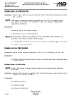
Страница 106: ...E If temperature remains above limits red annunciator ON and or abnormal oil pressure is indicated shut down affected engine If indications return to normal increase power on affected engine as desired Land as soon as practical ENGINE LOW OIL TEMPERATURE Indications Lower yellow caution annunciator ON at 10 C and below for NG 50 Procedures Allow engine oil temperature to increase to normal range b...

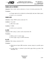
Страница 107: ...ine Land as soon as practical ENGINE CHIPS Indications Yellow CHIPS caution annunciator ON Conditions On ground Shut down engine Conditions In flight Land as soon as practical NG HIGH Indications Red warning or yellow caution annunciator ON Procedures Reduce power to normal range Check engine torque and EGT indications NG LOW Indications Red warning annunciator ON Procedures Check affected engine ...

Страница 108: ... line GENERATOR Indications Yellow GEN annunciator ON and LOAD is 0 Procedures L GEN or R GEN or both if dual generator failure switch RESET If GEN annunciator still ON OFF FOR AFFECTED GENERATOR S Continue flight If both generators failed Power switch ESNTL UNLESS FLIGHT CONDITIONS DICTATE OTHERWISE NOTE With both generators failed and the power switch in the ESNTL position a fully charged batter...

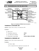
Страница 109: ...CIATOR YELLOW TRANSMISSION HIGH OIL PRESSURE CAUTION ANNUNCIATOR YELLOW TRANSMISSION LOW OIL PRESSURE CAUTION ANNUNCIATOR YELLOW TRANSMISSION LOW OIL PRESSURE WARNING ANNUNCIATOR RED FIRE WARNING ANNUNCIATOR RED F92 026 Figure 3 6 Transmission Malfunction Annunciators TRANSMISSION OIL TEMPERATURE HIGH Indications Upper yellow caution or red annunciator ON Procedures Reduce power Transmission oil p...

Страница 110: ...s demonstrated operation without oil for 30 minutes at a power setting of 56 Indications Lower yellow caution annunciator ON Procedures Land as soon as practical TRANSMISSION OIL PRESSURE HIGH Indications Upper yellow caution annunciator ON or red warning annunciator ON Procedures Monitor transmission oil pressure Land as soon as practical TRANSMISSION CHIPS Indications Yellow CHIPS annunciator ON...

Страница 111: ...age on the alphanumeric display Possible EEC caution indicator on Conditions Possible EEC noncritical fault resulting in transmission input torque mismatch of 18 or more NOTE For this message to be displayed both engines must be in the FLY mode neither engine can be out or operating in the manual mode and the aircraft must not be on the ground as determined by AOG logic Procedures Continue flight ...

Страница 112: ...ILTER IMPENDING BY PASS CAUTION YELLOW FUEL FILTER IMPENDING BY PASS CAUTION FUEL SHUTOFF VALVE YELLOW NOTE 1 FUEL SHUTOFF VALVE YELLOW NOTE 1 ÉÉ ÂÂ ÂÂ C INDICATES LOW FUEL PRESSURE ON BOTH FUEL BOOST PUMPS OR BOTH BOOSTER PUMPS IN OFF POSITION RED GREEN LOW FUEL WARNING TICK MARK RED LEFT SHOWN RIGHT OPPOSITE LOW FUEL CAUTION SEGMENT YELLOW FUEL QUANTITY SEGMENTS FUEL QUANTITY DIGITAL DISPLAY WHI...

Страница 113: ...arning tick mark s ON 140 KIAS MAXIMUM AND AVOID UNCOORDINATED TURNS MANEUVERS Indications Early display of low fuel warning tick marks above 220 LBS in hover and 160 LBS in cruise Conditions Fuel transfer system malfunction Procedures Place L BOOST and R BOOST switches OFF NOTE Expect engine flameout on side with early low fuel warning tick mark illuminated FUEL BOOST PUMP FAILURE Indications Alt...

Страница 114: ...ue the flight using consumption and time calculations DUAL FUEL PROBE FAILURE Indications Digital fuel quantity indicator blanked Vertical quantity segments blanked NOTE The low fuel warning tick mark indication remains operational with a dual fuel probe failure Procedures Continue the flight using consumption and time calculations NOTE Continuous display of fuel flow is available on the IIDS as a...

Страница 115: ... SHUTOFF VALVE MALFUNCTION Indications Two yellow bar segments flashing above and below the fuel flow line to the left or right of center Conditions Fuel valve not fully opened closed Procedures In flight Continue flight Be prepared for affected engine to flame out Pre Start Fuel shutoff switch CYCLE OFF TO ON If no change in indication DO NOT ATTEMPT START ...

Страница 116: ...GGAGE DOOR OPEN CAUTION ANNUNCIATOR YELLOW IIDS MALFUNCTION CAUTION ANNUNCIATOR YELLOW HYDRAULIC SYSTEM PRESSURE OR HIGH TEMPERATURE CAUTION ANNUNCIATOR YELLOW CABIN HEAT WARNING ANNUNCIATOR RED BATTERY WARM CAUTION ANNUNCIATOR YELLOW BATTERY HOT WARNING ANNUNCIATOR RED ROTOR BRAKE CAUTION ANNUNCIATOR YELLOW F92 028 Figure 3 8 Caution Warning Cluster CABIN HEAT Indications Red CAB HEAT annunciator...

Страница 117: ...dures Shut down aircraft Service or replace battery prior to next flight Overheated battery can cause burns to personnel unless protective clothing and adequate tools are utilized In some instances the battery may cause a secondary fire or may rupture adding the further danger of electrolyte burns Exercise caution in dealing with an overheated battery Maintain extinguisher ready for use Do not use...

Страница 118: ...warm condition results in the battery being disconnected from the aircraft electrical system once a generator is placed on line Generator power alone is not sufficient to start an engine Procedures Utilize a GPU to start engines Power switch OFF after both generators are on line If BATT WARM annunciator remains ON for more than five minutes shutdown the aircraft Otherwise continue flight Service o...

Страница 119: ... land as soon as possible CABIN DOOR Indications Yellow CABIN DOOR annunciator ON Conditions On ground Procedures Close and safe lock door Conditions In the air Procedures Reduce airspeed to 60 KIAS Ref Section II Land as soon as practical and close and safe lock the door BAGGAGE DOOR Indications Yellow BAGGAGE DOOR annunciator ON Conditions On ground Procedures Close and safe lock door Conditions...

Страница 120: ... KIAS or less Reduce electrical load Land as soon as practical BATTERY DISCHARGE Indications BATT DISCHARGE message on IIDS alphanumeric display Conditions Battery bus voltage less than 26 volts Procedures Do not clear the BATT DISCHARGE message NOTE The IIDS will display the BATT DISCHARGE message whenever the Battery Bus Voltage is 26V for 5 seconds or 22V for 0 5 seconds Clearing the BATT DISCH...

Страница 121: ... the incorrect position Procedures NOTE In the event that the malfunction results in one door remaining closed after the aircraft has gone beyond the threshold airspeed of 47 KIAS the engine with the closed NACA door will indicate a higher EGT than the engine having the NACA door open Place NACA INLET switch in CLOSE if flying in falling or blowing snow Ref Section II NOTE Flight into falling or b...

Страница 122: ...ion of flight 3 16 VIBRATIONS Indications Sudden unusual or excessive vibrations occurring during flight Conditions The onset of unusual or excessive vibrations in the helicopter may be an indication of problems in the rotor or drive train systems Procedures LAND AS SOON AS POSSIBLE No further flights should be attempted until the cause of the vibration has been identified and corrected Indication...

Страница 123: ...removal Each cabin door window may be used as an emergency exit by pulling the emergency exit pull tab and pulling the window inward Ref Figure 3 9 EMERGENCY EXIT PULL TAB TO REMOVE WINDOW f92 029 EMERGENCY EXIT RELEASE COCKPIT DOOR FRAME LOOKING OUTBOARD RIGHT SIDE RIGHT SHOWN LEFT OPPOSITE 1 LOCATED ON UPPER COCKPIT DOOR FRAME 2 LOCATED ADJACENT TO COCKPIT DOOR ACCESS HANDLE CABIN DOOR EMERGENCY...

Страница 124: ...enter console or on the aft right hand side of the station 155 5 bulkhead It detaches from the mount ing bracket by unfastening the quick release clamps The extinguisher uses Halon 1211 extinguishing agent The fire extinguisher is equipped with a pressure gauge that indicates normal charge and overcharge pressures F92 030 Figure 3 10 Emergency Fire Extinguisher First Aid Kit The first aid kit is l...

Страница 125: ...CSP 902RFM207E 1 Emergency and Malfunction Procedures ROTORCRAFT FLIGHT MANUAL MD900 902 Configuration with PW 207E FAA Approved Reissue 2 Original 3 47 This page intentionally left blank ...

Страница 126: ...CSP 902RFM207E 1 ROTORCRAFT FLIGHT MANUAL MD900 902 Configuration with PW 207E Emergency and Malfunction Procedures FAA Approved Reissue 2 Original 3 48 This page intentionally left blank ...

Страница 127: ...e Mounted Typical 4 18 Figure 4 5 Circuit Breakers Baggage Compartment Mounted Typical 4 19 Figure 4 6 Collective Pitch Stick Controls 4 20 Figure 4 7 Cyclic Stick Grip 4 21 4 4 Engine Pre Start Cockpit Check 4 22 4 5 Engine Starting Automatic 4 24 4 6 Engine Runup 4 25 4 7 Before Takeoff 4 25 4 8 NOrmal Takeoff 4 26 4 9 Cruise 4 26 4 10 Slow Flight Approach 4 26 4 11 Landing 4 27 Figure 4 8 Tail ...

Страница 128: ...CSP 902RFM207E 1 ROTORCRAFT FLIGHT MANUAL MD900 902 Configuration with PW 207E Normal Procedures FAA Approved Reissue 2 Original 4 ii This page intentionally left blank ...

Страница 129: ...tion and evidence of corrosion These are the most common types of damage however checks should not be limited to these items Further checks shall be performed before the next flight if discrepancies are noted to determine if the aircraft is airworthy Flight is prohibited when unrepaired damage exists which makes the aircraft unairworthy Have a thorough understanding of operating limitations Ref Se...

Страница 130: ...CSP 902RFM207E 1 ROTORCRAFT FLIGHT MANUAL MD900 902 Configuration with PW 207E Normal Procedures FAA Approved Reissue 2 Original 4 2 f92 031 1A Figure 4 1 Pilot s Preflight Guide Sheet 1 of 2 ...

Страница 131: ...CSP 902RFM207E 1 ROTORCRAFT FLIGHT MANUAL MD900 902 Configuration with PW 207E Normal Procedures FAA Approved Reissue 2 Original 4 3 F92 031 2A Figure 4 1 Pilot s Preflight Guide Sheet 2 of 2 ...

Страница 132: ...ns REMOVE Main rotor blades CHECK EXTERIOR CHECKS FRONT Battery compartment front mounted bat tery only BATTERY CONNECTED SECURE Battery compartment door front mounted battery only CONDITION CLOSED Pitot tube s CONDITION FREE OF OBSTRUCTIONS Windscreen CONDITION Chin windscreen CONDITION Chin windscreen area CHECK PEDAL LINKAGES FOREIGN OBJECTS Fuselage Bottom Landing and searchlight SECURITY COND...

Страница 133: ...GED Move pedals by hand OBSERVE MOVEMENT OF THRUSTER Electrical master panel POWER switch BAT EXT IIDS panel CHECK LAMP TEST MODE B I T Fuel quantity CHECK NOTE The fuel quantity indication will not display actual fuel weight when the fuel system is topped off Remove fuel cap and pull lanyard to assure tank is full by noting fuel level on the inside of filler neck Ref SECTION VIII Fuel can be trap...

Страница 134: ...ERIFY PROPER OPERATION OF DRAIN VALVES Fuel drain door CLOSED Forward fuselage skin and steps CONDITION External power door front mounted bat tery only avionics access panel static port fuel cap SECURITY CONDITION Right side passenger door Upper and lower track and guide CHECK Door rollers CHECK OPERATION Door skin and glass CHECK Door stops pins CHECK Right side passenger compartment Upholstery C...

Страница 135: ... ductwork CHECK CONDITION Generator cooling ducts if installed CHECK CONDITION Transmission deck CHECK FOR FOREIGN OBJECTS AND SIGNS OF FLUID LEAKAGE Forward access door CHECK OPERATION AND CONDITION CLOSE Generator cooling inlet if installed CHECK RIGHT CENTER TRANSMISSION DECK Oil cooler Cooling air inlet NO OBSTRUCTIONS Oil cooler CHECK MOUNTING LEAKS AND CONDITION Air ducts CHECK MOUNTING AND ...

Страница 136: ...steps CHECK Engine air inlet w o particle separator Inlet screen CHECK NO OBSTRUCTIONS NACA inlet NO OBSTRUCTIONS Engine air inlet with particle separator Particle separator CHECK NO OBSTRUCTIONS Bypass door CLOSED CONDITION OF SEAL NACA inlet door CLOSED NO OBSTRUCTIONS Right Engine Engine oil access door CHECK CONDITION Engine oil level CHECK NOTE To reduce the possibility of over servicing and ...

Страница 137: ...ange links CHECK Striker plates and rollers CHECK Inner flexbeam attach points CHECK Flexbeam lead and lag legs CHECK Upper and lower damper and damper caps CHECK Elastomeric feathering bearing CHECK Pitch change housing CHECK Blade attach pins bolts Check for upward or downward shift of installed blade retention bolts ADVISE MAINTENANCE IF SHIFT IS NOTED Check blade retention bolts for gap be twe...

Страница 138: ...od spring capsule CHECK NOTE Check piston rod for movement clips installed on outer bellcrank assembly and lanyards connected to clips If clips are bent and or lanyards are taut or piston rod moves in any direction advise maintenance Baggage compartment ceiling panel ZIP UP Baggage door CLOSED AND LATCHED Antennas externally mounted equip ment CHECK SECURITY ATTACHMENT TAILBOOM AND EMPENNAGE RIGHT...

Страница 139: ...ghness is noticed CAUTION Do not rotate cone beyond one half left right open Turning vanes CHECK TAILBOOM AND EMPENNAGE LEFT SIDE Horizontal stabilizer Horizontal stabilizer attach points CHECK Horizontal stabilizer fairing CHECK Antennas CHECK SECURITY ATTACHMENT Tail skid CHECK Vertical stabilizer CHECK Nav light CHECK Tailboom CHECK CONDITION Tailboom attach ring CHECK LEFT REAR FUSELAGE Fusela...

Страница 140: ... CHECK Antennas externally mounted equip ment CHECK SECURITY ATTACHMENT Left side passenger door Upper and lower track and guide CHECK Door rollers CHECK OPERATION Door skin and glass CHECK Door stops pins CHECK Left side passenger compartment Upholstery CHECK CONDITION Seats and seat belts CHECK OPERATION Loose equipment STOWED NOTE Nothing stowed under seats that are to be occupied FORWARD LEFT ...

Страница 141: ...manifold CHECK MOUNTING AND FLUID LEVEL System filters CHECK IMPENDING BYPASS INDICATORS REF SECTION VIII Lateral and collective hydraulic actua tors CHECK LEAKS MOUNTING Hydraulic hand pump CHECK LEAKS FITTINGS Hydraulic lines CHECK LEAKS FITTINGS Static mast supports CHECK ATTACHMENT Environmental control system if installed Evaporator CHECK Freon lines CHECK Air ductwork CHECK CONDITION Transmi...

Страница 142: ...K Fan drive shaft CHECK Rotor brake CHECK Transmission deck CHECK FOR FOREIGN OBJECTS AND SIGNS OF FLUID LEAKAGE Engine accessory gear box CHECK FITTINGS LINES CONNECTORS AND WIRING Engine oil filter CHECK BYPASS INDICATOR Transmission access door latches hinges and door CHECK OPERATION CLOSE Cabin door closed open and latched secured CHECK FUSELAGE LEFT TOP REAR Engine air inlet w o particle sepa...

Страница 143: ...il level always be checked within 10 minutes after engine shutdown Ref Section VIII Oil filler cap CHECK Engine cowling assembly CHECK 4 3 PILOT S PREFLIGHT CHECK Perform these checks prior subsequent flights of the same day Fluid levels CHECK Transmission deck signs of fluid leakage CHECK Air inlet screens particle separators CHECK Fuel cap access doors and panels CHECK Rotor blades CHECK BLADE R...

Страница 144: ... 2 Original 4 16 F92 032 1A IIDS AIRSPEED INDICATOR MAGNETIC COMPASS ALTIMETER IVSI FOOT HEATER CONTROL VALVE ALTERNATE STATIC SOURCE TOGGLE VALVE VSCS INDICATOR ATTITUDE INDICATOR TAKEOFF TIMING INDICATOR LIGHTS GPU DOOR LIGHT AFT MOUNTED BATTERY ONLY LOCATION TYPICAL Figure 4 2 Instrument Panel Single Pilot Typical ...

Страница 145: ... with PW 207E Normal Procedures FAA Approved Reissue 2 Original 4 17 f92 032 2a ALTERNATE STATIC SOURCE TOGGLE VALVE ALTERNATE STATIC SOURCE TOGGLE VALVE FOR LEFT SIDE NOTE 1 NOTE 2 NOTE 1 NOTE 2 PITOT STATIC INSTRUMENTS Figure 4 3 Instrument Panel Two Pilot Typical ...

Страница 146: ...ONTROL OVSP TEST L ENGINE R ENGINE OFF IDLE FLY TRAIN FUEL SYSTEM L BOOST R BOOST ON OFF BOTTLE PRI ALT LEFT OFF RIGHT OFF ON OFF FUEL SHUTOFF DISCHARGE O F F ELECTRICAL MASTER AVIONICS L GEN R GEN POWER ON OFF RESET RESET ON ON OFF OFF OFF BAT EXT ESNTL LIGHTING CONTROL LT MSTR CONSOLE IIDS FLOOD INSTR STROBE AREA POSN ON OFF OFF OFF ON OFF ON OFF OFF BOTH CKP CAB IPS HEAT AC VENT PITOT HEAT HYD ...

Страница 147: ... RH DC FDR FD SYN FLT DIR MODE SEL INVTR LEFT ESS BUS LEFT AVIONICS BUS RIGHT GENERATOR BUS ADF2 RADAR RT RADAR IND MKR BCN RAD ALT PA PWR COM 3 XPNDR 2 DIR GYRO 2 NAV 3 MVG MAP LIGHTING RIGHT AVIONICS BUS L R L R L R L R BST PUMP EEC RH FUEL LOW DETENT IGNTR CNSL POSN STROBE AREA AHRS 2 PRI AV MSTR AUX FUEL FIRE HRD SMOKE DET ENC ALT SRCH LGT HVR LGT NACA LH FUEL FUEL CAB AUD 5 V DIM NSUN CONT NS...

Страница 148: ...EC RESET SWITCH 3 TAKEOFF TIMER 4 HOVER LANDING AND SEARCHLIGHT SWITCHES 5 SEARCH LIGHT CONTROL SWITCH 6 GO AROUND SELECT SWITCH 7 COMMUNICATIONS SELECT SWITCH 8 YAW SYNCHRONIZATION SWITCH 9 AUTO PILOT YAW VERTICAL BEEP SWITCH 10 LEFT RIGHT ENGINE TWIST GRIPS 11 INDEX MARKS 12 ALIGNMENT MARK F927008 L R N O R M A L N O R M A L 1 11 12 3 2 Figure 4 6 Collective Pitch Stick Controls ...

Страница 149: ... FLIGHT MANUAL MD900 902 Configuration with PW 207E Normal Procedures FAA Approved Reissue 2 Original 4 21 CYCLIC TRIM FLOAT INFLATION SWITCH RADIO ICS F92 036 AUTO PILOT DISENGAGE CARGO HOOK RELEASE Figure 4 7 Cyclic Stick Grip ...

Страница 150: ...K Rotor brake STOWED Magnetic compass CHECK Flight instruments CHECK STATIC POSITION SET Collective Control Collective friction ON Collective stick position FULL DOWN If collective is not full down do not try to force down until hydraulic pressure increases during start Twistgrip alignment marks aligned with index mark CHECK LDG HVR lights OFF Key switch ON Essential bus panels Circuit breakers IN...

Страница 151: ... GEN and R GEN ON OFF FOR GPU START POWER OFF Fuel system panel L BOOST AND R BOOST OFF LEFT RIGHT FUEL SHUTOFF ON COVER CLOSED Engine control panel L ENGINE and R ENGINE OFF ELECTRICAL POWER ON Electrical master panel POWER BAT EXT NOTE If helicopter has the aft battery option the yellow GPU light will be ON when a GPU is used for electrical power IIDS Monitor BIT FIRE WARNING ANNUNCIATORS ON FOR...

Страница 152: ...imum overtemperature limits during start Ref Section II abort the start as follows Engine control switch OFF fuel boost pump OFF monitor IIDS displays If lightoff is not attained with an increase of EGT and NG within 10 seconds turn fuel boost pump OFF and place the engine control switch to OFF Following a 30 second fuel drain period perform a 30 second dry motoring run Ref Section VIII before att...

Страница 153: ...ngine GPU start only L GEN R GEN ON GPU DISCONNECT Yellow GPU indicator light aft mounted battery only OUT 4 6 ENGINE RUNUP Electrical master panel Avionics ON AS DESIRED Engine control panel L ENGINE and R ENGINE FLY 4 7 BEFORE TAKEOFF Cyclic response check Move cyclic stick and observe rotor tip for correct movement Collective friction AS DESIRED Primary and secondary IIDS displays CHECK ADVISOR...

Страница 154: ...ve and or may register key inputs twice This condition will clear itself after a brief interval Care should be taken when using the arrow keys or to scroll between menu and submenu names or between data and message items Pressing the arrow keys too fast may result in scrolling past the desired menu or message displayed The arrow keys should be pressed only after the menu item or message changes in...

Страница 155: ... 66 9 15 NOSE UP LANDING ATTITUDES IN EXCESS OF 9 66 WILL RESULT IN THE TAIL SKID CONTACTING THE LANDING SURFACE NOSE UP LANDING ATTITUDES IN EXCESS OF 9 15 WILL RESULT IN THE TAIL SKID CONTACTING THE LANDING SURFACE Figure 4 8 Tail Skid Bumper Flare Angle and Landing Surface Clearance Running landing Maximum recommended ground contact speed is 30 knots for smooth hard sur face Avoid rapid lowerin...

Страница 156: ...g the rotor is 50 knots Collective stick FULL DOWN FRICTION ON Cyclic stick TRIM TO NEUTRAL REF FIGURE 4 9 Pedals NEUTRAL Engine control panel L ENGINE and R ENGINE SET TO IDLE All unnecessary electrical equipment OFF Utility panel Heat OFF AC if installed OFF Pitot heat if installed OFF IPS if installed OFF Lighting control panel AS DESIRED Electrical master panel Avionics master switch OFF L GEN...

Страница 157: ...ol panel L ENGINE and R ENGINE OFF ENG OUT indications CHECK IIDS Do not use collective pitch to slow rotor Should an abnormal vibration occur as the NR passes through 40 to 35 advise maintenance before further flights This vibration may indicate that possible damage to the flexbeam has occurred NOTE Check that compressor decelerates freely Abnormal noise or rapid run down rapid loss of NG may ind...

Страница 158: ...ormal operating RPM when the engine is not driving the rotor system Full control of the helicopter during these conditions may be limited IIDS CHECK FOR INDICATIONS OR MESSAGES NOTE Wait for NG to reach 0 before entering the IIDS Time Summary menu to check LST FLT TIME or TOT FLT HR Failure to wait for NG to reach 0 may result in incorrect time records Electrical master panel POWER OFF AT 0 NG Key...

Страница 159: ...east possible noise while flying the helicopter Takeoff Takeoff using maximum takeoff power at the speed for best rate of climb Ref Section V Proceed away from noise sensitive areas If takeoff must be made over noise sensitive area distance altitude is the best form of noise suppression Cruise Maintain 1000 feet minimum altitude where possible Maintain speed of no more than 110 KIAS over populated...

Страница 160: ... NOTE Refer to Section VI for weight and balance data with doors opened or removed One or both cabin doors may be opened or closed in flight at airspeeds up to 60 KIAS For sustained flight with the cabin doors open use of the cabin door hold open device is required Ref Figure 4 10 CABIN DOOR RESTRAINT FITTING LEFT SIDE LOOKING INBOARD f92 038 NOTE THE CABIN DOOR HOLD OPEN DEVICE OPERATES BY ATTACH...

Страница 161: ... in training if the power requested is above the limiters as would happen in a real OEI condition IDLE mode If rescaling of the TORQUE and EGT displays and activation of the ENG OUT warning is desired the pilot should select IDLE instead of TRAIN for OEI train ing In the event the opposite engine should fail during this time the pilot must select FLY on the engine control switch to bring the good ...

Страница 162: ...edures FAA Approved Reissue 2 Revision 4 4 34 4 17 FUEL SYSTEM Capacities Fuel System JET A 1097 lb 498 kg 161 3 US gallons 611L total capacity 1078 lb 489 kg 158 5 US gallons 600L useable JET B 1048 lb 476 kg 161 3 US gallons 611L total capacity 1030 lb 467 kg 158 5 US gallons 600L useable ...

Страница 163: ...t VY OEI MCP and 3500 LB Gross Weight 5 10 Figure 5 5 Single Engine Rate of Climb and Descent From 10 C to 50 C at VY OEI MCP and 3500 LB Gross Weight 5 11 Figure 5 6 Single Engine Rate of Climb and Descent From 0 C to 36 C at VY OEI MCP and 4000 LB Gross Weight 5 12 Figure 5 7 Single Engine Rate of Climb and Descent From 10 C to 50 C at VY OEI MCP and 4000 LB Gross Weight 5 13 Figure 5 8 Single E...

Страница 164: ...eight 5 26 Figure 5 20 Rate of Climb AEO at VY MCP 4000 lb Gross Weight 5 27 Figure 5 21 Rate of Climb AEO at VY MCP 4500 lb Gross Weight 5 28 Figure 5 22 Rate of Climb AEO at VY MCP 5000 lb Gross Weight 5 29 Figure 5 23 Rate of Climb AEO at VY MCP 5500 lb Gross Weight 5 30 Figure 5 24 Rate of Climb AEO at VY MCP 6000 lb Gross Weight 5 31 Figure 5 25 Rate of Climb AEO at VY MCP 6250 lb Gross Weigh...

Страница 165: ...oot Skid Height IPS Installed Takeoff Power Cabin Heat Off 5 50 Figure 5 43 Hover Ceiling IGE 3 5 Foot Skid Height IPS Installed Takeoff Power Cabin Heat On 5 51 Figure 5 44 Hover Ceiling OGE IPS Installed Takeoff Power Cabin Heat Off 5 52 Figure 5 45 Hover Ceiling OGE IPS Installed Takeoff Power Cabin Heat On 5 53 5 9 Hover Ceiling OEI 5 54 Figure 5 46 Hover Ceiling OGE Standard Inlet 2 5 Minute ...

Страница 166: ...CSP 902RFM207E 1 ROTORCRAFT FLIGHT MANUAL MD900 902 Configuration with PW 207E Performance Data FAA Approved Reissue 2 Revision 5 5 iv This page intentionally left blank ...

Страница 167: ...ions such as airspeed weight altitude temperature wind velocity and engine power available Data is applicable to the basic helicopter without any optional equipment installed unless otherwise noted Serial numbers SNs 900 00141 and subsequent Maximum gross weight 6770 lb 3071 kg Serial numbers 900 00140 and prior If TB900 044 has been accomplished Maximum gross weight is 6770 lb 3071 kg NOTE If TB9...

Страница 168: ...Part 36 J noise requirements at the certified maximum gross weight of 6770 lb for level flight at 0 9 VH Table 5 1 FAA Noise Levels MD900 NOISE CHARACTERISTICS 6770 lb 3071 kg ENGINE PW 207E Configuration Clean aircraft doors on no external kits 0 9 VH SL at 25 C 90 KTAS 81 49 dBA The MD900 meets the FAR Part 36 J noise requirements at the certified maximum gross weight of 6500 lb for level flight...

Страница 169: ...line move to left and note density altitude Pressure altitude is found by setting 29 92 1013 mb in Kolsman window altimeter error To determine true airspeed convert indicated airspeed IAS to calibrated airspeed CAS utilizing the Airspeed Calibration Curve Ref Figure 5 2 Read value on right of chart opposite known density altitude Multiply CAS by this value to determine true airspeed Examples Find ...

Страница 170: ...20 10 0 10 20 30 40 2000 0 2000 4000 6000 8000 10000 12000 14000 16000 18000 20000 DENSITY ALTITUDE FEET 0 98 1 00 1 02 1 04 1 06 1 08 1 10 1 12 1 14 1 16 1 18 1 20 1 22 1 24 1 26 1 28 1 30 1 32 1 34 1 36 TEMPERATURE C TEMPERATURE F 50 60 40 30 20 10 0 10 20 30 40 50 60 70 80 90 100 110 f927 009 120 130 140 Figure 5 1 Density Altitude Chart ...

Страница 171: ...orrected for position error equals calibrated airspeed CAS Use of chart Use the chart as illustrated by the example To determine calibrated airspeed the pilot must know the indicated airspeed NOTE The example below refers to Figure 5 2 Example Wanted Calibrated airspeed Known Indicated airspeed 120 knots Method Enter the bottom of the chart at the indicated airspeed of 120 knots Move up to the air...

Страница 172: ...D900 902 Configuration with PW 207E Performance Data 5 6 FAA Approved Reissue 2 Revision 5 f927 010 160 140 120 100 80 60 40 20 160 140 120 100 80 60 40 20 INDICATED AIRSPEED KNOTS CALIBRATED AIRSPEED KNOTS Figure 5 2 Airspeed Calibration Curve ...

Страница 173: ... use for the best rate of climb at any given density altitude Use of Chart Use the chart as illustrated by the example below Example Wanted Best rate of climb Known Density altitude 8 000 feet Method Enter the left side of chart at the known density altitude of 8 000 feet Move to the right to the airspeed calibration curve and then directly down to read 60 knots indicated airspeed IAS as the best ...

Страница 174: ...ion with PW 207E Performance Data 5 8 FAA Approved Reissue 2 Revision 5 f927 011 20 25 30 35 40 45 50 55 60 65 70 75 80 INDICATED AIRSPEED KNOTS 0 2000 4000 6000 8000 10000 12000 14000 16000 18000 20000 DENSITY ALTITUDE FEET Figure 5 3 Best Rate of Climb Speed VY ...

Страница 175: ...of climb speed NOTE These charts based on an electrical load of 30 heater OFF and air conditioning OFF Use of Chart The following example explains the correct use of the chart in Figure 5 4 Use of Charts Use the chart as illustrated by the example below Example Wanted Rate of climb Known Pressure altitude 4000 feet Known Outside air temperature 0 C Method Enter the left side of chart ref Figure 5 ...

Страница 176: ...MB AT VY FT MIN F927 012 11 1000 0 1000 2000 3000 4000 5000 6000 7000 8000 9000 10000 11000 12000 13000 14000 15000 16000 17000 18000 19000 20000 200 0 200 400 600 800 1000 1200 1400 1600 1800 Continuous OEI Power Vy 3500 lb 0 10 20 30 36 OAT 5C MAXIMUM OAT LIMIT Figure 5 4 Single Engine Rate of Climb and Descent From 36 C to 0 C at VY OEI MCP and 3500 LB Gross Weight ...

Страница 177: ... 3000 4000 5000 6000 7000 8000 9000 10000 11000 12000 13000 14000 15000 16000 17000 18000 19000 20000 200 0 200 400 600 800 1000 1200 1400 1600 1800 2000 40 6 OAT LIMIT 52 OAT LIMIT 30 40 50 20 10 0 10 PRESSURE ALTITUDE FEET RATE OF CLIMB AT VY FT MIN OAT 5C Figure 5 5 Single Engine Rate of Climb and Descent From 10 C to 50 C at VY OEI MCP and 3500 LB Gross Weight ...

Страница 178: ...B AT VY FT MIN F927 012 2 1000 0 1000 2000 3000 4000 5000 6000 7000 8000 9000 10000 11000 12000 13000 14000 15000 16000 17000 18000 19000 20000 600 400 200 0 200 400 600 800 1000 1200 1400 1600 0 10 20 30 36 OAT 5C MAXIMUM OAT LIMIT Continuous OEI Power Vy 4000 lb Figure 5 6 Single Engine Rate of Climb and Descent From 0 C to 36 C at VY OEI MCP and 4000 LB Gross Weight ...

Страница 179: ...00 0 1000 2000 3000 4000 5000 6000 7000 8000 9000 10000 11000 12000 13000 14000 15000 16000 17000 18000 19000 20000 600 400 200 0 200 400 600 800 1000 1200 1400 1600 40 6 OAT LIMIT 52 OAT LIMIT 30 40 50 20 10 0 10 PRESSURE ALTITUDE FEET OAT 5C Figure 5 7 Single Engine Rate of Climb and Descent From 10 C to 50 C at VY OEI MCP and 4000 LB Gross Weight ...

Страница 180: ...00 3000 4000 5000 6000 7000 8000 9000 10000 11000 12000 13000 14000 15000 16000 17000 18000 19000 20000 600 400 200 0 200 400 600 800 1000 1200 1400 1600 0 10 36 OAT 5C RATE OF CLIMB AT VY FT MIN F927 012 3 Continuous OEI Power Vy and 4500 lb 20 30 MAXIMUM OAT LIMIT Figure 5 8 Single Engine Rate of Climb and Descent From 36 C to 0 C at VY OEI MCP and 4500 LB Gross Weight ...

Страница 181: ... 3000 4000 5000 6000 7000 8000 9000 10000 11000 12000 13000 14000 15000 16000 17000 18000 19000 20000 600 400 200 0 200 400 600 800 1000 1200 1400 1600 PRESSURE ALTITUDE FEET OAT 5C RATE OF CLIMB AT VY FT MIN 52 OAT LIMIT 40 6 OAT LIMIT 30 40 50 20 10 0 10 Figure 5 9 Single Engine Rate of Climb and Descent From 10 C to 50 C at VY OEI MCP and 4500 LB Gross Weight ...

Страница 182: ...B AT VY FT MIN F927 012 6 1000 0 1000 2000 3000 4000 5000 6000 7000 8000 9000 10000 11000 12000 13000 14000 15000 16000 17000 18000 19000 20000 600 400 200 0 200 400 600 800 1000 1200 1400 1600 0 10 36 OAT 5C Continuous OEI Power Vy 5000 lb MAXIMUM OAT LIMIT 30 20 Figure 5 10 Single Engine Rate of Climb and Descent From 36 C to 0 C at VY OEI MCP and 5000 LB Gross Weight ...

Страница 183: ... 3000 4000 5000 6000 7000 8000 9000 10000 11000 12000 13000 14000 15000 16000 17000 18000 19000 20000 600 400 200 0 200 400 600 800 1000 1200 1400 1600 PRESSURE ALTITUDE FEET OAT 5C RATE OF CLIMB AT VY FT MIN 30 40 50 20 10 0 10 40 6 OAT LIMIT 52 OAT LIMIT Figure 5 11 Single Engine Rate of Climb and Descent From 10 C to 50 C at VY OEI MCP and 5000 LB Gross Weight ...

Страница 184: ...OF CLIMB AT VY FT MIN F927 012 8 1000 0 1000 2000 3000 4000 5000 6000 7000 8000 9000 10000 11000 12000 13000 14000 15000 16000 17000 18000 19000 20000 600 400 200 0 200 400 600 800 1000 1200 1400 1600 0 10 36 OAT 5C Continuous OEI Power Vy and 5500 lb 30 20 Figure 5 12 Single Engine Rate of Climb and Descent From 36 C to 0 C at VY OEI MCP and 5500 LB Gross Weight ...

Страница 185: ... 3000 4000 5000 6000 7000 8000 9000 10000 11000 12000 13000 14000 15000 16000 17000 18000 19000 20000 600 400 200 0 200 400 600 800 1000 1200 1400 1600 PRESSURE ALTITUDE FEET OAT 5C RATE OF CLIMB AT VY FT MIN 30 40 50 20 10 0 10 40 6 OAT LIMIT 52 OAT LIMIT Figure 5 13 Single Engine Rate of Climb and Descent From 10 C to 50 C at VY OEI MCP and 5500 LB Gross Weight ...

Страница 186: ... 2000 3000 4000 5000 6000 7000 8000 9000 10000 11000 12000 13000 14000 15000 16000 17000 18000 19000 20000 600 400 200 0 200 400 600 800 1000 1200 1400 1600 PRESSURE ALTITUDE FEET OAT 5C RATE OF CLIMB AT VY FT MIN 30 20 36 30 40 50 20 10 0 10 52 OAT LIMIT 40 6 OAT LIMIT Figure 5 14 Single Engine Rate of Climb and Descent at VY OEI MCP and 5750 LB Gross Weight ...

Страница 187: ...2000 3000 4000 5000 6000 7000 8000 9000 10000 11000 12000 13000 14000 15000 16000 17000 18000 19000 20000 600 400 200 0 200 400 600 800 1000 1200 1400 1600 PRESSURE ALTITUDE FEET OAT 5C RATE OF CLIMB AT VY FT MIN 40 6 OAT LIMIT 52 OAT LIMIT 36 30 20 30 40 50 20 10 0 10 Figure 5 15 Single Engine Rate of Climb and Descent at VY OEI MCP and 6000 LB Gross Weight ...

Страница 188: ...5000 6000 7000 8000 9000 10000 11000 12000 13000 14000 15000 16000 17000 18000 19000 20000 600 400 200 0 200 400 600 800 1000 1200 1400 1600 40 6 OAT LIMIT 52 OAT LIMIT 30 40 50 20 10 0 10 20 36 30 PRESSURE ALTITUDE FEET RATE OF CLIMB AT VY FT MIN Continuous OEI Power Vy 6250 lb OAT 5C Figure 5 16 Single Engine Rate of Climb and Descent at VY OEI MCP and 6250 LB Gross Weight ...

Страница 189: ...8000 9000 200 100 0 100 200 300 400 500 30 C 36 C 20 C 10 C 0 C 10 C 20 C 30 C 5000 FT HD 40 C 40 6 C OAT LIMIT 50 C 52 C OAT LIMIT THIS CHART BASED ON ELECTRICAL LOAD OF 30 HEATER OFF AND AIR CONDITIONING OFF PRESSURE ALTITUDE FEET OAT RATE OF CLIMB AT VY FT MIN Continuous OEI Power Vy 6500 lb Figure 5 17 Single Engine Rate of Climb and Descent at VY OEI MCP 6500 LBS Gross Weight ...

Страница 190: ...207E 1 ROTORCRAFT FLIGHT MANUAL MD900 902 Configuration with PW 207E Performance Data 5 24 FAA Approved Reissue 2 Revision 5 Figure 5 18 Single Engine Rate of Climb and Descent at VY OEI MCP 6770 lb Gross Weight ...

Страница 191: ...igure 5 35 at the best rate of climb speed NOTE These charts based on an electrical load of 30 heater OFF and air conditioning OFF Use of Chart The following example explains the correct use of the chart in Figure 5 19 Example Wanted Rate of climb Known Pressure altitude 3000 feet Known Outside air temperature 20 C Method Enter the left side of chart at the known pressure altitude of 3000 feet Mov...

Страница 192: ... 4000 5000 6000 7000 8000 9000 10000 11000 12000 13000 14000 15000 16000 17000 18000 19000 20000 1300 1500 1700 1900 2100 2300 2500 2700 2900 3100 3300 3500 3700 3900 4100 4300 4500 Rate of Climb ft min Pressure Altitude ft MCP VY 3 500 lb 30 40 50 20 10 0 10 20 30 40 6 OAT LIMIT 52 OAT LIMIT 36 OAT 5C Figure 5 19 Rate of Climb AEO at VY MCP 3500 lb Gross Weight ...

Страница 193: ...3000 4000 5000 6000 7000 8000 9000 10000 11000 12000 13000 14000 15000 16000 17000 18000 19000 20000 800 1000 1200 1400 1600 1800 2000 2200 2400 2600 2800 3000 3200 3400 3600 3800 Rate of Climb ft min Pressure Altitude ft MCP VY 4000 lb 30 40 50 20 10 0 10 20 30 40 6 OAT LIMIT 52 OAT LIMIT 36 OAT 5C Figure 5 20 Rate of Climb AEO at VY MCP 4000 lb Gross Weight ...

Страница 194: ...00 3000 4000 5000 6000 7000 8000 9000 10000 11000 12000 13000 14000 15000 16000 17000 18000 19000 20000 400 600 800 1000 1200 1400 1600 1800 2000 2200 2400 2600 2800 3000 3200 Rate of Climb ft min Pressure Altitude ft 30 40 50 20 10 0 10 30 40 6 OAT LIMIT 52 OAT LIMIT 36 OAT 5C MCP VY 4500 lb 20 Figure 5 21 Rate of Climb AEO at VY MCP 4500 lb Gross Weight ...

Страница 195: ...2000 3000 4000 5000 6000 7000 8000 9000 10000 11000 12000 13000 14000 15000 16000 17000 18000 19000 20000 0 200 400 600 800 1000 1200 1400 1600 1800 2000 2200 2400 2600 2800 Rate of Climb ft min Pressure Altitude ft MCP VY 5000 lb 30 40 50 20 10 0 10 30 40 6 OAT LIMIT 52 OAT LIMIT 36 OAT 5C 20 Figure 5 22 Rate of Climb AEO at VY MCP 5000 lb Gross Weight ...

Страница 196: ... 2000 3000 4000 5000 6000 7000 8000 9000 10000 11000 12000 13000 14000 15000 16000 17000 18000 19000 20000 0 200 400 600 800 1000 1200 1400 1600 1800 2000 2200 2400 Rate of Climb ft min Pressure Altitude ft OAT 5C MCP VY 5500 lb 30 50 20 10 0 10 30 40 6 OAT LIMIT 52 OAT LIMIT 36 OAT 5C 20 40 Figure 5 23 Rate of Climb AEO at VY MCP 5500 lb Gross Weight ...

Страница 197: ... 0 1000 2000 3000 4000 5000 6000 7000 8000 9000 10000 11000 12000 13000 14000 15000 16000 17000 18000 19000 20000 0 200 400 600 800 1000 1200 1400 1600 1800 2000 2200 Rate of Climb ft min Pressure Altitude ft MCP VY 6000 lb 30 50 20 10 0 10 30 40 6 OAT LIMIT 52 OAT LIMIT 36 OAT 5C 20 40 Figure 5 24 Rate of Climb AEO at VY MCP 6000 lb Gross Weight ...

Страница 198: ...6b 0 1000 2000 3000 4000 5000 6000 7000 8000 9000 10000 11000 12000 13000 14000 15000 16000 17000 18000 19000 20000 0 200 400 600 800 1000 1200 1400 1600 1800 2000 Rate of Climb ft min Pressure Altitude ft MCP VY 6250 lb 30 50 20 10 0 10 30 40 6 OAT LIMIT 52 OAT LIMIT 36 OAT 5C 20 40 Figure 5 25 Rate of Climb AEO at VY MCP 6250 lb Gross Weight ...

Страница 199: ...2000 3000 4000 5000 6000 7000 8000 9000 10000 11000 12000 13000 14000 15000 16000 17000 18000 19000 20000 0 200 400 600 800 1000 1200 1400 1600 1800 2000 Rate of Climb ft min Pressure Altitude ft OAT o C 52 OAT LIMIT 40 6 OAT LIMIT 14000 FT HD LIMIT MCP VY 6500 lb 30 50 20 10 0 10 30 36 20 40 Figure 5 26 Rate of Climb AEO at VY MCP 6500 lb Gross Weight ...

Страница 200: ...d Reissue 2 Revision 5 F927 013 9 0 1000 2000 3000 4000 5000 6000 7000 8000 9000 10000 1200 1300 1400 1500 1600 1700 1800 MCP VY 6770 lb Pressure Altitude ft Rate of Climb and Descent FT MIN OAT 3000 FT HD 36 C 10 C 0 C 10 C 20 C 30 C 40 C 30 C 20 C 40 6 C OAT LIMIT Figure 5 27 AEO at VY MCP 6770 lb Gross Weight ...

Страница 201: ... 4000 5000 6000 7000 8000 9000 10000 11000 12000 13000 14000 15000 16000 17000 18000 19000 20000 1900 2100 2300 2500 2700 2900 3100 3300 3500 3700 3900 4100 4300 4500 4700 4900 5100 Rate of Climb ft min Pressure Altitude ft 30 40 50 20 10 0 10 OAT 5C 20 30 36 40 6 OAT LIMIT 52 OAT LIMIT TOP VY 3 500 lb Figure 5 28 Rate of Climb AEO at VY TOP 3500 lb Gross Weight ...

Страница 202: ...0 4000 5000 6000 7000 8000 9000 10000 11000 12000 13000 14000 15000 16000 17000 18000 19000 20000 1300 1500 1700 1900 2100 2300 2500 2700 2900 3100 3300 3500 3700 3900 4100 4300 4500 Rate of Climb ft min Pressure Altitude ft TOP VY 4000 lb 50 40 6 OAT LIMIT 52 OAT LIMIT 30 40 20 10 0 10 20 30 36 OAT 5C Figure 5 29 Rate of Climb AEO at VY TOP 4000 lb Gross Weight ...

Страница 203: ...3000 4000 5000 6000 7000 8000 9000 10000 11000 12000 13000 14000 15000 16000 17000 18000 19000 20000 900 1100 1300 1500 1700 1900 2100 2300 2500 2700 2900 3100 3300 3500 3700 3900 Rate of Climb ft min Pressure Altitude ft TOP VY 4500 lb 50 40 6 OAT LIMIT 52 OAT LIMIT 30 40 20 10 0 10 20 OAT 5C 30 36 Figure 5 30 Rate of Climb AEO at VY TOP 4500 lb Gross Weight ...

Страница 204: ...00 3000 4000 5000 6000 7000 8000 9000 10000 11000 12000 13000 14000 15000 16000 17000 18000 19000 20000 500 700 900 1100 1300 1500 1700 1900 2100 2300 2500 2700 2900 3100 3300 Rate of Climb ft min Pressure Altitude ft TOP VY 5000 lb 50 40 6 OAT LIMIT 52 OAT LIMIT 30 40 20 10 0 10 20 30 36 OAT 5C Figure 5 31 Rate of Climb AEO at VY TOP 5000 lb Gross Weight ...

Страница 205: ... 2000 3000 4000 5000 6000 7000 8000 9000 10000 11000 12000 13000 14000 15000 16000 17000 18000 19000 20000 0 200 400 600 800 1000 1200 1400 1600 1800 2000 2200 2400 2600 2800 Rate of Climb ft min Pressure Altitude ft TOP VY 5500 lb 50 40 6 OAT LIMIT 52 OAT LIMIT 30 40 20 10 0 10 20 30 36 OAT 5C Figure 5 32 Rate of Climb AEO at VY TOP 5500 lb Gross Weight ...

Страница 206: ...00 2000 3000 4000 5000 6000 7000 8000 9000 10000 11000 12000 13000 14000 15000 16000 17000 18000 19000 20000 0 200 400 600 800 1000 1200 1400 1600 1800 2000 2200 2400 2600 Rate of Climb ft min Pressure Altitude ft TOP VY 6000 lb 50 40 6 OAT LIMIT 52 OAT LIMIT 30 40 20 10 0 10 20 30 36 OAT 5C Figure 5 33 Rate of Climb AEO at VY TOP 6000 lb Gross Weight ...

Страница 207: ...1000 2000 3000 4000 5000 6000 7000 8000 9000 10000 11000 12000 13000 14000 15000 16000 17000 18000 19000 20000 0 200 400 600 800 1000 1200 1400 1600 1800 2000 2200 2400 Rate of Climb ft min Pressure Altitude ft TOP VY 6250 lb 50 40 6 OAT LIMIT 52 OAT LIMIT 30 40 20 10 0 10 20 30 36 OAT 5C Figure 5 34 Rate of Climb AEO at VY TOP 6250 lb Gross Weight ...

Страница 208: ... 3000 4000 5000 6000 7000 8000 9000 10000 11000 12000 13000 14000 15000 16000 300 500 700 900 1100 1300 1500 1700 1900 2100 Pressure Altitude ft OAT o C f927 021 7a Rate of Climb and Descent ft min TOP VY 6500 LB 50 30 40 20 10 0 10 20 36 30 52 OAT LIMIT 40 6 OAT LIMIT 14000 FT HD LIMIT Figure 5 35 Rate of Climb AEO at VY TOP 6500 lb Gross Weight ...

Страница 209: ... 2 Revision 5 5 43 F927 021 8 0 1000 2000 3000 4000 5000 6000 7000 8000 9000 10000 1800 1850 1900 1950 2000 2050 Pressure Altitude ft Rate of Climb and Descent FT MIN OAT 3000 FT HD 40 6 C OAT LIMIT MCP VY 6770 lb 40 C 30 C 20 C 10 C 0 C 10 C 20 C 30 C 36 C Figure 5 36 Rate of Climb AEO at VY TOP 6770 lb Gross Weight ...

Страница 210: ...t IGE or out of ground effect OGE both engines operating at take off power for known conditions of pressure altitude and outside air temperature OAT or alternately the maximum hover ceiling for a known gross weight and outside air temperature Refer to Figure 5 37 for HIGE operations in crosswind conditions ÕÕÕÕÕÕÕÕÕÕÕÕÕ ÕÕÕÕÕÕÕÕÕÕÕÕÕ ÕÕÕÕÕÕÕÕÕÕÕÕÕ ÕÕÕÕÕÕÕÕÕÕÕÕÕ ÕÕÕÕÕÕÕÕÕÕÕÕÕ ÕÕÕÕÕÕÕÕÕÕÕÕÕ ÕÕÕÕÕÕÕÕ...

Страница 211: ...still allows the rotorcraft to operate at a maximum gross weight of 6500 lb 2948 kg Follow the example shown below Use of Chart The following example explains the correct use of the IGE Chart in Figure 5 38 Example Wanted Maximum gross weight for hover at 3 5 feet skid height at takeoff power Known PA 7000 feet OAT 30 C cabin heat off and A C on 25 electrical load Method Enter the chart at 30 C OA...

Страница 212: ... ABOVE BELOW 15 DECREASE INCREASE WEIGHT CAPABILITY 35 LBS PER 10 CHANGE IN ELECTRICAL LOAD REDUCE WEIGHT CAPABILITY 40 LBS WITH A C ON 13000 14000 15000 12000 PRESSURE ALTITUDE FEET 15300 HD AIRCRAFT WITHOUT GENERATOR COOLING MODIFICATION 16000 50 40 30 20 10 0 10 20 30 40 50 60 11000 10000 9000 7000 6000 8000 5000 4000 3000 OAT C NOTE MAXIMUM INTERNAL GROSS WEIGHT 6770 LB WEIGHTS IN EXCESS OF 67...

Страница 213: ...000 16000 8000 MAXIMUM TEMPERATURE FOR CABIN HEAT ON PRESSURE ALTITUDE FEET 15300 HD AIRCRAFT WITHOUT GENERATOR COOLING MODIFICATION 6000 5000 THIS CHART BASED ON WINDS 3KTS OR LESS AND 15 ELECTRICAL LOAD FOR ELECTRICAL LOADS ABOVE BELOW 15 DECREASE INCREASE WEIGHT CAPABILITY 35 LBS PER 10 CHANGE IN ELECTRICAL LOAD REDUCE WEIGHT CAPABILITY 40 LBS WITH A C ON NOTE MAXIMUM INTERNAL GROSS WEIGHT 6770...

Страница 214: ...00 12000 16000 8000 5000 4000 3000 2000 1000 0 PRESSURE ALTITUDE FEET THIS CHART BASED ON WINDS 3KTS OR LESS AND 15 ELECTRICAL LOAD FOR ELECTRICAL LOADS ABOVE BELOW 15 DECREASE INCREASE WEIGHT CAPABILITY 35 LBS PER 10 CHANGE IN ELECTRICAL LOAD REDUCE WEIGHT CAPABILITY 40 LBS WITH A C ON 15300 HD GROSS WEIGHT LB AIRCRAFT WITHOUT GENERATOR COOLING MODIFICATION NOTE MAXIMUM INTERNAL GROSS WEIGHT 6770...

Страница 215: ...IS CHART BASED ON WINDS 3KTS OR LESS AND 15 ELECTRICAL LOAD FOR ELECTRICAL LOADS ABOVE BELOW 15 DECREASE INCREASE WEIGHT CAPABILITY 35 LBS PER 10 CHANGE IN ELECTRICAL LOAD REDUCE WEIGHT CAPABILITY 40 LBS WITH A C ON 7000 MAXIMUM TEMPERATURE FOR CABIN HEAT ON PRESSURE ALTITUDE FEET 15300 HD GROSS WEIGHT LB 6000 5000 4000 3000 AIRCRAFT WITHOUT GENERATOR COOLING MODIFICATION NOTE MAXIMUM INTERNAL GRO...

Страница 216: ...E BELOW 15 DECREASE INCREASE WEIGHT CAPABILITY 35 LBS PER 10 CHANGE IN ELECTRICAL LOAD REDUCE WEIGHT CAPABILITY 40 LBS WITH A C ON GROSS WEIGHT LB OAT C 50 40 30 20 10 0 10 20 30 40 50 60 PRESSURE ALTITUDE FEET 15300 HD 11000 10000 9000 7000 6000 13000 14000 15000 12000 8000 5000 16000 AIRCRAFT WITHOUT GENERATOR COOLING MODIFICATION 2000 5000 3000 4000 NOTE MAXIMUM INTERNAL GROSS WEIGHT 6770 LB WE...

Страница 217: ...15 DECREASE INCREASE WEIGHT CAPABILITY 35 LBS PER 10 CHANGE IN ELECTRICAL LOAD REDUCE WEIGHT CAPABILITY 40 LBS WITH A C ON 50 40 30 20 10 0 10 20 30 40 50 60 GROSS WEIGHT LB OAT C PRESSURE ALTITUDE FEET 15300 HD 13000 14000 15000 12000 16000 AIRCRAFT WITHOUT GENERATOR COOLING MODIFICATION 11000 10000 9000 8000 7000 MAXIMUM TEMPERATURE FOR CABIN HEAT ON 6000 5000 NOTE MAXIMUM INTERNAL GROSS WEIGHT ...

Страница 218: ...13000 14000 15000 12000 16000 8000 5000 4000 3000 2000 1000 PRESSURE ALTITUDE FEET 0 15300 HD THIS CHART BASED ON WINDS 3KTS OR LESS AND 15 ELECTRICAL LOAD FOR ELECTRICAL LOADS ABOVE BELOW 15 DECREASE INCREASE WEIGHT CAPABILITY 35 LBS PER 10 CHANGE IN ELECTRICAL LOAD REDUCE WEIGHT CAPABILITY 40 LBS WITH A C ON AIRCRAFT WITHOUT GENERATOR COOLING MODIFICATION NOTE MAXIMUM INTERNAL GROSS WEIGHT 6770 ...

Страница 219: ... 5000 4000 3000 PRESSURE ALTITUDE FEET THIS CHART BASED ON WINDS 3KTS OR LESS AND 15 ELECTRICAL LOAD FOR ELECTRICAL LOADS ABOVE BELOW 15 DECREASE INCREASE WEIGHT CAPABILITY 35 LBS PER 10 CHANGE IN ELECTRICAL LOAD REDUCE WEIGHT CAPABILITY 40 LBS WITH A C ON 15300 HD 12000 OAT C MAXIMUM TEMPERATURE FOR CABIN HEAT ON GROSS WEIGHT LB AIRCRAFT WITHOUT GENERATOR COOLING MODIFICATION NOTE MAXIMUM INTERNA...

Страница 220: ...he chart in Figure 5 46 Example 1 Zero wind Wanted Maximum gross weight for hover OGE at 2 5 minute OEI power Known HP 4000 FT OAT 10 C Method Enter the chart at 10 C and move right to the 4000 HP curve At this point move up and read from the gross weight scale 5275 LB Example 2 Headwind NOTE It is essential that reliable wind information be available prior to determining hover Additionally only t...

Страница 221: ...ART IS BASED ON OEI CONDITIONS 2 5 MIN POWER WIND FROM THE NOSE 30 DEGREES AND CABIN HEAT OFF HEADWIND KNOTS GROSS WEIGHT 6700 3700 3900 4100 4300 4500 4700 4900 5100 5300 5500 5700 5900 6100 6300 6500 POUNDS 0 5 10 15 20 25 30 GROSS WEIGHT POUNDS 50 40 30 20 10 0 10 20 30 40 50 60 OAT C PRESSURE ALTITUDE FEET 4000 4100 4200 4300 4400 4500 4600 4700 4800 4900 5000 5100 5200 5300 5400 5500 3900 380...

Страница 222: ...700 5900 6100 6300 6500 4000 4100 4200 4300 4400 4500 4600 4700 4800 4900 5000 5100 5200 5300 5400 5500 GROSS WEIGHT POUNDS 3900 3800 3700 50 40 30 20 10 0 10 20 30 40 50 60 OAT C PRESSURE ALTITUDE FEET POUNDS 0 5 10 15 20 25 30 THIS CHART IS BASED ON OEI CONDITIONS 2 5 MIN POWER WIND FROM THE NOSE 30 DEGREES AND CABIN HEAT OFF NOTE WIND SPEEDS ARE UNFAC TORED APPLY FACTOR AS REQUIRED BY OPERATION...

Страница 223: ...AVOID AREAS IN CHART A APPLY ÔÔÔÔÔÔÔÔÔÔÔÔÔ ÔÔÔÔÔÔÔÔÔÔÔÔÔ ÔÔÔÔÔÔÔÔÔÔÔÔÔ ÔÔÔÔÔÔÔÔÔÔÔÔÔ ÔÔÔÔÔÔÔÔÔÔÔÔÔ ÔÔÔÔÔÔÔÔÔÔÔÔÔ ÔÔÔÔÔÔÔÔÔÔÔÔÔ ÔÔÔÔÔÔÔÔÔÔÔÔÔ ÔÔÔÔÔÔÔÔÔÔÔÔÔ ÔÔÔÔÔÔÔÔÔÔÔÔÔ ÔÔÔÔÔÔÔÔÔÔÔÔÔ ÔÔÔÔÔÔÔÔÔÔÔÔÔ ÔÔÔÔÔÔÔÔÔÔÔÔÔ ÔÔÔÔÔÔÔÔÔÔÔÔÔ ÔÔÔÔÔÔÔÔÔÔÔÔÔ ÔÔÔÔÔÔÔÔÔÔÔÔÔ 0 1000 2000 3000 4000 5000 6000 7000 8000 9000 10000 11000 4900 5100 5300 5500 5700 5900 6100 6300 6500 DENSITY ALTITUDE FEET 6700 CHART B Figure 5...

Страница 224: ...IIDS POWER CHECK menu or other previous power assurance checks in the TREND LOG under AIRCRAFT MONITOR menu NOTE This power check procedure refers to the automated IIDS power check If unable to perform the automated power check use the manual power check method found in paragraph 5 12 PERFORM POWER ASSURANCE CHK POWER CHECK VIEW LAST POWER ASSURANCE CHK L PA CHK NG X X L PA CHK EGT XX X AUTOMATIC ...

Страница 225: ...gine is to be checked first press the to access the right engine menu RT ENG TQ XXX X TIME 30 SEC Stabilize engine torque at 3 of the ENG TQ value displayed for 30 seconds The IIDS provides a countdown from 30 seconds on the alphanumeric display during data acquisition The countdown is started after the torque value is within the 3 range for more than 2 seconds NOTE Counter will reset to 15 second...

Страница 226: ...ltitude Use the Engine Torque Chart Ref Figure 5 50 todetermine the torque value to be utilized based on the OAT and pressure altitude recorded in the previous step Increase collective and stabilize at the predetermined torque value After one minute record the EGT and NG from the IIDS Use the EGT Chart Ref Figure 5 51 and the NG Chart Ref Figure 5 52 or Figure 5 53 to determine maximum values of E...

Страница 227: ...etting for the above noted conditions is determined to be Engine torque 71 Utilizing the EGT and NG Power Check Charts Ref Figure 5 51 and Figure 5 52 the maximum values for EGT and NG for the above noted conditions is determined to be EGT 791 C NG 92 5 After stabilizing the torque at 71 for one minute you record the following EGT and NG readings from the IIDS EGT 770 C NG 92 Subtract the observed...

Страница 228: ... 207E Performance Data 5 62 FAA Approved Reissue 2 Revision 5 f927 018 20 10 0 10 20 30 40 35 40 45 50 55 60 65 70 75 80 ENGINE TORQUE AMBIENT TEMPERATURE C 50 12000 6000 8000 14000 16000 10000 4000 2000 30 36 SEA LEVEL PRESSURE ALTITUDE FEET Figure 5 50 Engine Torque Chart ...

Страница 229: ...IGHT MANUAL MD900 902 Configuration with PW 207E FAA Approved Reissue 2 Revision 5 5 63 500 550 600 650 700 750 800 850 900 40 20 0 20 40 60 PRESSURE ALTITUDE FEET 4000 8000 SEA LEVEL 16000 12000 AMBIENT TEMPERATURE C f927 019 Figure 5 51 EGT Chart ...

Страница 230: ...Performance Data 5 64 FAA Approved Reissue 2 Revision 5 81 82 83 84 85 86 87 88 89 90 91 92 93 94 95 96 40 30 20 10 0 10 20 30 40 50 NG AMBIENT TEMPERATURE C PRESSURE ALTITUDE FEET 8000 16000 12000 4000 SEA LEVEL f927 020 1 Figure 5 52 NG Chart NG read from Secondary IIDS Display ...

Страница 231: ...th PW 207E FAA Approved Reissue 2 Revision 5 5 65 f927 020 2 83 84 85 86 87 88 89 90 91 92 93 94 95 96 97 40 30 20 10 0 10 20 30 40 50 60 AMBIENT TEMPERATURE C NG PRESSURE ALTITUDE FEET 20000 16000 12000 8000 SEA LEVEL 4000 Figure 5 53 NG Chart NG read from Third Level Power Check Menu ...

Страница 232: ...CSP 902RFM207E 1 ROTORCRAFT FLIGHT MANUAL MD900 902 Configuration with PW 207E Performance Data 5 66 FAA Approved Reissue 2 Revision 5 This page intentionally left blank ...

Страница 233: ...able 6 3 Cabin Doors Open Weight Data 6 7 6 4 Longitudinal Weight and Balance Determination Passenger Configuration 6 8 EXAMPLE I Longitudinal CG Determination Passenger 6 8 6 5 Longitudinal Loading of Cargo 6 9 EXAMPLE II Longitudinal CG Determination Cargo 6 9 6 6 Permissible Lateral Loadings Passenger Configuration 6 10 EXAMPLE III Lateral CG Determination Passenger 6 10 6 7 Lateral Loading of ...

Страница 234: ...Configuration with PW 207E Weight and Balance Data Original 6 ii Reissue 2 PARAGRAPH PAGE Table 6 8 Weight and Longitudinal Moments Cargo 6 20 Table 6 9 Weight and Lateral Moments Pilot and Passengers 6 21 Table 6 10 Weight and Lateral Moments Cargo 6 22 ...

Страница 235: ...y 1500 pounds not to exceed 115 pounds per square foot Baggage compartment limit sta 234 3 to 256 9 500 pounds not to exceed 115 lbs per square foot Ultimate load factors cargo restraint Forward 17 G s Lateral 8 G s Center of Gravity Limits NOTE Lateral is right of centerline lateral is left of centerline when looking forward Table 6 1 Center of Gravity Limits Gross Weight Longitudinal C G Limit S...

Страница 236: ...CHART A THE MAXIMUM LONGITUDINAL C G LIMIT AS DEPICTED BY THE DASHED LINE IN CHART B APPLIES 3000 3500 4000 4500 5000 5500 6000 6500 3 2 1 0 1 2 3 4 5 6 7 3000 3500 4000 4500 5000 5500 6000 6500 194 196 198 200 202 204 206 208 GROSS WIGHT LBS GROSS WIGHT LBS CHART A LATERAL C G STATION IN EXPANDED CG LIMITS CHART B LONGITUDINAL C G STATION IN 5100 LBS NORMAL CG LIMITS NORMAL CG LIMITS Figure 6 1 C...

Страница 237: ...ght and Balance Data Original 6 3 Reissue 2 15 85 15 85 STA 130 7 STA 173 0 0 0 19 0 19 0 STA 213 0 STA 245 6 CG OF PILOT OR COPILOT PASSENGER CG REAR FACING PASSENGERS CG FWD FACING PASSENGERS CL OF BAGGAGE COMPARTMENT F92 052 CG CABIN STA 193 0 0 0 Figure 6 2 Reference Coordinates ...

Страница 238: ... 60 220 200 180 160 140 120 100 80 60 WL 106 FLOOR BL 24 BEAM BL 8 5 BEAM 50 50 220 200 180 160 140 120 100 80 60 STA 155 5 FRAME STA 230 5 FRAME 3 16 STA 292 817 WL 147 WL 159 ROOF DECK 60 80 100 120 140 180 200 220 240 260 280 300 320 340 360 380 400 420 440 460 STA 199 25 WL 207 97 160 5 0 WL 106 FLOOR JACKING POINTS 480 Figure 6 3 Station Diagram ...

Страница 239: ...UT REGISTRATION NUMBER N9XXXX PAGE 4 OF 4 DESCRIPTION OF ARTICLE WEIGHT CHANGE RUNNING TOTAL BASIC AIRCRAFT ADDED REMOVED WEIGHT LONG ARM WEIGHT LONG ARM Form HOQ014 rev 5 00 12 23 xx 01 09 xx 01 09 xx X ACTUAL BASIC WEIGHT REVISED CALCULATED BASIC WEIGHT FIXED BALLAST IN NOSE 5 0 87 6 438 3277 8 210 2 689103 210 4 3272 8 688665 f92 054 A OR MOCIFICATION LAT ARM LONG MOMENT LAT MOMENT WEIGHT LONG ...

Страница 240: ... 440 460 STA 199 25 WL 207 97 160 5 0 WL 106 FLOOR JACKING POINTS 480 NOTE IN A LEVEL ATTITUDE MAIN ROTOR MAST IS TILTED 3 DEG FORWARD WEIGHING POINT AVE SCALE READING LBS TARE OR CALIB CORR LBS NET WEIGHT LBS LONGITUDINAL ARM IN LATERAL ARM IN LONGITUDINAL MOMENT IN LBS LATERAL MOMENT IN LBS Forward 869 7 0 0 869 7 154 0 9 3 133929 8066 Aft Right 1289 5 0 0 1289 5 233 0 23 3 300454 29981 Aft Left...

Страница 241: ...k file Record the weight and balance effects of these changes in the Basic Weight and Balance Record inserted in this section Use the balance and station diagrams shown as an aid for weight and balance changes Use the following tables to assist in determining weight and balance effects with doors opened or removed Table 6 2 Cockpit Cabin and Baggage Compartment Doors Weight Data ITEM WEIGHT LB LON...

Страница 242: ...ef EXAMPLE I NOTE If loadings are not symmetrical about the aircraft centerline determine lateral CG s as described in Paragraphs 6 6 and 6 7 EXAMPLE I Longitudinal CG Determination Passenger ITEM WEIGHT LB STATION ARM MOMENT IN LB Basic Weight from Figure 6 4 3272 8 688665 Pilot 170 130 70 22219 Copilot Passenger 170 130 70 22219 Passenger Rear Facing R H 170 173 0 29410 Passenger Rear Facing L H...

Страница 243: ... Figure 6 3 Obtain the cargo moment Cargo Moment Cargo Weight X Cargo CG Perform weight and balance as previously described for passenger configura tion EXAMPLE II Longitudinal CG Determination Cargo ITEM WEIGHT LB STATION ARM MOMENT IN LB Basic Weight from Figure 6 4 3272 8 688665 Pilot 170 130 7 22219 Copilot Passenger 170 130 7 22219 Cargo 750 190 0 142500 1 Zero Fuel Weight Add Fuel Jet A 4362...

Страница 244: ...ceed as follows Obtain the basic weight and longitudinal moment from The Basic Weight and Bal ance Record Ref Figure 6 4 For pilot and passenger longitudinal and lateral center of gravity stations see Figure 6 2 EXAMPLE III Lateral CG Determination Passenger ITEM WEIGHT LB STATION ARM MOMENT IN LB Basic Weight from Figure 6 4 3272 8 1309 Pilot 170 15 85 2695 Passenger Rear Facing R H 170 19 00 323...

Страница 245: ... by using the correctnumber of tiedowns in accor dance with Table 6 4 Locate restraint loops in accordance with Figure 6 6 NOTE Cargo carried in the baggage compartment shall not be higher than 36 inches To assure that cargo is properly secured refer to Table 6 4 The numbered tiedown location is located in the far left column of Table 6 4 with their respective restraint values in the six columns t...

Страница 246: ...6 12 Reissue 2 EXAMPLE IV Tiedown 500 pounds of cargo in the main cabin LATERAL TIEDOWN No FORWARD LEFT RIGHT 1 220 14 220 2 20 40 13 20 40 4 130 40 11 130 40 5 120 220 10 120 220 ____ ____ ____ TOTAL 540 520 520 Since all three values exceed the weight of the cargo 500 pounds the cargo is sufficiently restrained ...

Страница 247: ...RAL LEFT LATERAL RIGHT 1 156 8 27 0 220 2 174 9 25 0 20 40 3 193 0 25 0 130 20 4 211 1 25 0 130 40 5 229 2 27 0 120 220 6 229 2 11 0 50 240 7 229 2 8 0 50 240 8 229 2 8 0 50 240 9 229 2 11 0 50 240 10 229 2 27 0 120 220 11 211 1 25 0 130 40 12 193 0 25 0 130 20 13 174 9 25 0 20 40 14 156 8 27 0 220 15 156 8 11 0 240 16 156 8 8 0 240 17 156 8 8 0 240 18 156 8 11 0 240 19 232 9 21 6 90 185 20 251 0 ...

Страница 248: ...a Original 6 14 Reissue 2 CARGO RESTRAINT LOCATION 1 2 3 4 5 6 7 8 9 10 12 13 14 15 16 17 18 19 20 21 23 24 25 26 27 28 FWD LEFT RIGHT 11 F92 056 TIEDOWNS 25 AND 26 ARE D RINGS LOCATED AT WL 154 5 TIEDOWNS 19 THRU 28 ARE D RINGS TIE DOWNS 27 AND 28 ARE LOCATED AT WL 155 0 22 Figure 6 6 Cargo Restraint ...

Страница 249: ...25 450 475 500 525 550 575 600 625 650 675 700 725 750 775 800 825 850 875 900 925 950 975 1000 FUEL WEIGHT POUNDS F92 057 1 NOTES WEIGHTS AND MOMENTS BASED ON JET A FUEL 2 TOTAL WEIGHT OF FUEL IS DEPENDENT UPON THE SPECIFIC GRAVITY AND TEMPERATURE VARIATION SHOULD BE ANTICIPATED IN GAUGE READINGS WHEN TANKS ARE FULL 3 FUEL CG VARIES WITH QUANTITY ASTM D 1655 AT 6 8 POUNDS PER U S GALLON 1025 1050...

Страница 250: ... 225 250 275 300 325 350 375 400 425 450 475 500 525 550 575 600 625 650 675 700 725 750 775 800 825 850 875 900 925 950 975 1000 NOTES WEIGHTS AND MOMENTS BASED ON JET B FUEL 2 TOTAL WEIGHT OF FUEL IS DEPENDENT UPON THE SPECIFIC GRAVITY AND TEMPERATURE VARIATION SHOULD BE ANTICIPATED IN GAUGE READINGS WHEN TANKS ARE FULL 3 FUEL CG VARIES WITH QUANTITY ASTM D 1655 AT 6 5 POUNDS PER U S GALLON 1025...

Страница 251: ...8 4 89697 75 510 188 7 96237 80 544 188 9 102787 85 578 189 2 109343 90 612 189 4 115905 95 646 189 6 122470 100 680 189 8 129038 105 714 189 9 135607 110 748 190 1 142176 115 782 190 2 148744 120 816 190 3 155309 125 850 190 4 161872 130 884 190 5 168431 135 918 190 6 174986 140 952 190 7 181537 145 986 190 8 188033 150 1020 190 8 194626 155 1054 190 9 201165 160 1088 190 9 207710 NOTES 1 TOTAL W...

Страница 252: ...88 4 85739 75 488 188 7 91992 80 520 188 9 98252 85 553 189 2 104519 90 585 189 4 110791 95 618 189 6 117067 100 650 189 8 123345 105 683 189 9 129624 110 715 190 1 135903 115 748 190 2 142181 120 780 190 3 148457 125 813 190 4 154730 130 845 190 5 161000 135 878 190 6 167266 140 910 190 7 173528 145 943 190 8 179786 150 975 190 8 186040 155 1008 190 9 192290 160 1040 190 9 198538 NOTES 1 TOTAL WE...

Страница 253: ...ENT IN LB MOMENT IN LB MOMENT IN LB 100 13070 17300 21300 120 15684 20760 25560 140 18298 24220 29820 160 20912 27680 34080 180 23526 31140 38340 200 26140 34600 42600 220 28754 38060 46860 240 31368 41520 51120 BAGGAGE LBS AFT BAGGAGE STA 245 6 BAGGAGE LBS AFT BAGGAGE STA 245 6 MOMENT IN LB MOMENT IN LB 100 24560 320 78592 120 29472 340 83504 140 34384 360 88416 160 39296 380 93328 180 44208 400 ...

Страница 254: ...8400 180 28800 32400 36000 39600 43200 200 32000 36000 40000 44000 48000 220 35200 39600 44000 48400 52800 240 38400 43200 48000 52800 57600 260 41600 46800 52000 57200 62400 280 44800 50400 56000 61600 67200 300 48000 54000 60000 66000 72000 320 51200 57600 64000 70400 76800 340 54400 61200 68000 74800 81600 360 57600 64800 72000 79200 86400 380 60800 68400 76000 83600 91200 400 64000 72000 80000...

Страница 255: ...TA 19 00 MOMENT IN LB MOMENT IN LB MOMENT IN LB 100 1585 1900 1900 110 1744 2090 2090 120 1902 2280 2280 130 2061 2470 2470 140 2219 2660 2660 150 2378 2850 2850 160 2536 3040 3040 170 2695 3230 3230 180 2853 3420 3420 190 3012 3610 3610 200 3170 3800 3800 210 3329 3990 3990 220 3487 4810 4810 230 3646 4370 4370 240 3804 4560 4560 250 3963 4750 4750 260 4121 4940 4940 270 4280 5130 5130 280 4438 5...

Страница 256: ... 450 900 1350 1800 100 500 1000 1500 2000 110 550 1100 1650 2200 120 600 1200 1800 2400 130 650 1300 1950 2600 140 700 1400 2100 2800 150 750 1500 2250 3000 160 800 1600 2400 3200 170 850 1700 2550 3400 180 900 1800 2700 3600 l90 950 1900 2850 3800 200 1000 2000 3000 4000 210 1050 2100 3150 4200 220 1100 2200 3300 4400 230 1150 2300 3450 4600 240 1200 2400 3600 4800 250 1250 2500 3750 5000 260 130...

Страница 257: ...ls Subsystem 7 13 Figure 7 7 Upper Flight Controls Subsystem 7 14 Figure 7 8 Anti Torque Controls Subsystem Sheet 1 of 3 7 16 Figure 7 8 Anti Torque Controls Subsystem Sheet 2 of 3 7 17 Figure 7 8 Anti Torque Controls Subsystem Sheet 3 of 3 7 18 Figure 7 9 VSCS Control Subsystem 7 19 7 7 Hydraulic Systems 7 20 Figure 7 10 Hydraulic System Installation 7 21 Figure 7 11 Hydraulic System Block Diagra...

Страница 258: ...7 25 Alphanumeric Display 7 47 Table 7 1 Automatic Alphanumeric Display Warning Caution Advisory Messages 7 47 7 16 IIDS Data Storage 7 49 7 17 Balance Monitoring System 7 52 Figure 7 26 Balance Monitoring System Installation 7 52 7 18 IIDS Menu Structures 7 53 Figure 7 27 IIDS Top Level Menus 7 53 Figure 7 28 Time Summary 7 54 Figure 7 29 Balance Monitor Main Rotor Balance 7 55 Figure 7 30 Balanc...

Страница 259: ...issue 2 PARAGRAPH PAGE Figure 7 41 Aircraft Monitor Exceedance Log Menu 7 67 Figure 7 42 Aircraft Monitor Trend Log 7 68 Figure 7 43 Aircraft Monitor Fault Log Menu 7 69 Figure 7 44 Aircraft Monitor IIDS Setup 7 70 Figure 7 45 Fuel Calibration 7 71 Figure 7 46 Set Engine Parameters 7 72 Figure 7 47 Set Time Date 7 72 ...

Страница 260: ...ROTORCRAFT FLIGHT MANUAL MD900 902 Configuration with PW 207E CSP 902RFM207E 1 Systems Description Original 7 iv Reissue 2 This page intentionally left blank ...

Страница 261: ...tor On board systems monitoring and computerized track and balance The patented NOTAR anti torque system provides many benefits It results in low noise by locating the fan in the fuselage and eliminating the conventional noisy tail rotor provides outstanding safety because there is no exposed tail rotor and improved directional controllability over that of the conventional tail rotor helicopter Th...

Страница 262: ... ENGINE RIGHT HAND ENGINE LEFT HAND EMPENNAGE ASSEMBLY UPPER COWLING AND FAIRINGS TRANSMISSION ASSEMBLY TAILBOOM ASSEMBLY ANTI TORQUE THRUSTER BAGGAGE COMPARTMENT DOOR ANTI TORQUE ASSEMBLY CABIN DOOR LANDING GEAR ASSEMBLY COCKPIT DOOR FLIGHT CONTROLS FUSELAGE STRUCTURE ASSEMBLY COCKPIT DOOR CABIN DOOR F92 058 Figure 7 1 Helicopter Major Components ...

Страница 263: ...iedown fittings are positioned high on the sides of the fuselage in line with the forward edge of the cabin doors and one on the fuselage centerline just above the baggage compartment door Fabric socks are used to capture the blade tips for tying them to the landing gear crosstubes 7 2 FUSELAGE The fuselage contains the cockpit cabin baggage compartment fuel cell NOTAR fan support and ducts and av...

Страница 264: ...nsmission mount consists of an eight legged metal truss that sup ports the mast base and the static mast The transmission gearbox mounts beneath the mast base and the rotor turns on the static mast tube on a set of tapered roller thrust bearings Two of the truss tubes on the right side of the aircraft are removable for transmission maintenance Graphite epoxy cowlings and access doors on top of the...

Страница 265: ...l control is produced by airflow out of the controllable direct jet thruster at the end of the tailboom The empennage consists of the horizontal stabilizer with upper and lower moveable vertical stabilizers located at each tip The horizontal and vertical surfaces are graph ite epoxy The horizontal stabilizer has an inverted NACA 2412 airfoil with a fixed incidence of 1 degree A trailing edge Gurne...

Страница 266: ...nd Aft Crosstubes Provide energy absorbing capabilities during nor mal or severe landings Forward and Aft Saddle Assemblies Provide a means to attach the crosstube assemblies to the fuselage attachment points Side Stop Clamp Assemblies Prevent side movement of the crosstube assemblies Forward Spacer Fittings Forward attachments for the skid tubes and forward crosstube assembly Skid Tubes Provide l...

Страница 267: ...CATOR FIRST NOTCH SECOND NOTCH GREEN RED EMPTY FULL F92 060 RESERVOIR INDICATOR CLOCKING TYPICAL SKID TUBE FORWARD SPACER FITTING AFT SADDLE ASSEMBLY AFT CROSSTUBE SIDE STOP CLAMP ASSEMBLY PLUG DAMPER ASSEMBLY AFT ABRASION STRIP FORWARD CROSSTUBE FORWARD SADDLE ASSEMBLY STEP FORWARD ABRASION STRIP GROUND HANDLING ATTACH POINTS MID ABRASION STRIP Figure 7 3 Landing Gear ...

Страница 268: ...the hub by five bolts The pitchcase is a hollow elliptically shaped graphite epoxy tube that surrounds the flexbeam and is attached to both the flexbeam and the blade at its outboard end by a pair of expandable bushing bolts The pitchcase provides flapwise chord wise and torsional stiffness to the inboard end of the blade and serves to transmit the feathering control motions to the blade The pitch...

Страница 269: ...r between them The plates are grooved to accept the flexbeams and are bolted together with the same bolts that attach the flexbeams The hub mounts to the static mast by a pair of grease lubricated tapered roller bearings A splined drive plate bolts to the top of the hub and is driven by the main rotor shaft that rotates inside the mast This static mast rotor support configuration has been used suc...

Страница 270: ...num foil co cured onto the surface of the pitchcase dual jumpers across all joints and twin carbon brushes for hub to mast continuity 7 6 FLIGHT CONTROLS The flight controls provide a means of controlling blade pitch of the main rotor in flight and during ground operations The helicopter is equipped with dual pilot controls The flight controls integrate pilot inputs from the cyclic collective and ...

Страница 271: ...ontrol and thrust As the collective stick assembly is moved control linkages increase or de crease the rotor blades angle of attack The collective pitch system includes two automatic control features Conventional anticipatory circuit into the Engine Electronic Controls EEC to prepare them for an upcoming change of power demanded by the changing collective pitch position and vertical stabilizer inc...

Страница 272: ...LY LATERAL GRADIENT SPRING ASSEMBLY LONGITUDINAL CONTROLS CONTROL ROD ASSEMBLY LATERAL TRIM ACTUATOR LATERAL CONTROLS BRACKET ASSEMBLY LONGITUDINAL TRIM ACTUATOR CRANK ASSEMBLY LONGITUDINAL GRADIENT SPRING ASSEMBLY EXPANDABLE DIAMETER BOLT ASSEMBLY REF UPPER DECK DUAL LATERAL ROD END BALL BEARING COCKPIT LATERAL CONTROLS TUBE ASSEMBLY DUAL LONGITUDINAL CONTROL ROD ASSEMBLY LONGITUDINAL BRACKET ASS...

Страница 273: ...Y COLLECTIVE BRACKET ASSEMBLY COLLECTIVE CONTROL ROD ASSEMBLY COLLECTIVE BELLCRANK ASSEMBLY LONGITUDINAL COLLECTIVE FOD COVER UPPER DECK COLLECTIVE CONTROL ROD ASSEMBLY COLLECTIVE HYDRAULIC SERVOACTUATOR COLLECTIVE FRICTION RELEASE SWITCH COLLECTIVE INTERCONNECT CONTROL ROD ASSEMBLY INTERCONNECT CABLE ASSEMBLY COLLECTIVE BELLCRANK ASSEMBLY COPILOT COLLECTIVE STICK ASSEMBLY SENSOR BRACKET ASSEMBLY ...

Страница 274: ... cockpit floor in the forward right hand cockpit cabin bulkhead and in the cabin ceiling to transmit the control motions to the dual tandem hy draulic actuators that operate the rotor control mixer and the swashplate SWASHPLATE ASSEMBLY MIXER ASSEMBLY SCISSORS DRIVE LINK ASSEMBLY COLLECTIVE DRIVE LINK ASSEMBLY LATERAL ANTI TORQUE DRIVE LINK ASSEMBLY ROTOR CONTROL PITCH LINK ASSEMBLY F92 062 3 Figu...

Страница 275: ... the tail boom as the thruster nozzle opens and closes The hydraulic actuator operates the NOTAR fan blade pitch through a pushrod bellcrank cam linkage and the thruster rotation through a push pull type cable along the length of the tailboom and a local tension cable loop at the thruster The pedals do not control the vertical stabilizers Attached to the lower directional crank assembly is the ped...

Страница 276: ...DUAL CONTROL DIRECTIONAL PEDAL ASSEMBLY RIGHT HEEL REST SUPPORT LEFT HEEL REST SUPPORT HEEL REST ASSEMBLY DIRECTIONAL CONTROL ROD ASSEMBLY LOWER CLOSET DIRECTIONAL BELLCRANK ASSEMBLY AFT DIRECTIONAL CONTROL ROD ASSEMBLY HEEL REST ASSEMBLY REF UPPER DECK DIRECTIONAL BELLCRANK ASSEMBLY PEDAL ADJUSTMENT HANDLE PEDAL CRANK ASSEMBLY DIRECTIONAL PEDAL LINK ASSEMBLY PEDAL ANTICIPATOR Figure 7 8 Anti Torq...

Страница 277: ...RECTIONAL CONTROL CABLE ASSEMBLY DIRECTIONAL CONTROLS CONTROL ROD ASSEMBLY DIRECTIONAL CONTROL ROD ASSEMBLY SPLITTER ASSEMBLY DIRECTIONAL BRACKET ASSEMBLY DIRECTIONAL BELLCRANK ASSEMBLY FOD COVER CONTROL BRACKET ASSEMBLY DIRECTIONAL BELLCRANK ASSEMBLY ANTI TORQUE SERVO ACTUATOR DIRECTIONAL BRACKET ASSEMBLY UPPER DECK DIRECTIONAL CONTROL ROD ASSEMBLY DIRECTIONAL CONTROL ROD ASSEMBLY OUTER BELLCRANK...

Страница 278: ...EMBLY THRUSTER STATIONARY CONE ASSEMBLY THRUSTER CONTROL DRUM ASSEMBLY THRUSTER DRUM BRACKET ASSEMBLY THRUSTER CONTROL SECTOR ASSEMBLY THRUSTER CONTROL ROD ASSEMBLY THRUSTER BUILDUP ASSEMBLY ROTATING CONE ASSEMBLY TAILBOOM ASSEMBLY DIRECTIONAL CONTROL CABLE ASSEMBLY THRUSTER CONTROL ROD ASSEMBLY VIEW ROTATED Figure 7 8 Anti Torque Controls Subsystem Sheet 3 of 3 ...

Страница 279: ...h vertical stabilizers Instrumentation control includes a dual indica tor on the instrument panel to show incidence angle of the two vertical stabilizers a LEFT STAB FAIL RIGHT STAB FAIL or TOTAL STAB FAIL yellow CAUTION annunciator on the IIDS alphanumeric display and two OFF ON TEST L VSCS R switches on the utility panel and a YAW SYNC switch located on the collective control module Ref Section ...

Страница 280: ...s one for each cyclic pitch function and one for collective pitch of the main rotor The 1 system operates only the main rotor controls while the 2 system operates the main rotor controls and also the NOTAR anti torque control system The main rotor actuators are mounted forward of the main rotor while the anti torque actuator is mounted in the cabin ceiling just aft of the right hand cabin door A h...

Страница 281: ... 2 PUMP SYSTEM NO 1 PUMP GSE PANELS F92 064 SYSTEM NO 1 MANIFOLD SYSTEM NO 2 MANIFOLD PRESSURE TRANSDUCER SYSTEM SELECT SOLENOID SYSTEM NO 2 PUMP SYSTEM NO 1 PUMP GSE PANELS F927 023 SYSTEM NO 1 MANIFOLD SYSTEM NO 2 MANIFOLD FLUID LEVEL SIGHT GAUGE FILTER BOWL PRESSURE FILTER BOWL RETURN BLEED VALVE SAMPLING VALVE TEMPERATURE SWITCH Figure 7 10 Hydraulic System Installation ...

Страница 282: ...7 22 Reissue 2 GSE PANEL F92 065 HAND PUMP OPTIONAL MANIFOLD RESERVOIR VARIABLE DELIVERY PUMP VARIABLE DELIVERY PUMP MANIFOLD RESERVOIR COLLECTIVE SERVO ACTUATOR LONGITUDINAL SERVO ACTUATOR LATERAL SERVO ACTUATOR DIRECTIONAL SERVO ACTUATOR SYSTEM 1 SYSTEM 2 GSE PANEL Figure 7 11 Hydraulic System Block Diagram ...

Страница 283: ...n It incorporates a master cylinder operated by the brake handle in the cockpit and the actuator that operates the disc brake on the back side of the transmission where the NOTAR drive shaft connects A yellow BRAKE caution annunciator in the IIDS secondary display screen warns if the brake is not fully disengaged MASTER CYLINDER WITH INTEGRAL RESERVOIR HYDRAULIC TUBE CONTROL LINKAGE F92 066 BRAKE ...

Страница 284: ...3 and Figure 7 14 Each engine is mounted to the fuselage upper deck by a three point adjustable titanium mount The air inlet which is in the middle of the engine is located inside a titanium walled inlet plenum that leads from a flush mounted inlet in the side of the cowling The combuster end of the engine is surrounded by titanium firewalls forward aft inboard side and below It is covered by a fa...

Страница 285: ...SSURE PORT OIL TEMPERATURE PORT TORQUE SENSOR RH OIL LEVEL SIGHT GLASS LH OIL LEVEL SIGHT GLASS CHIP DETECTOR OIL FILTER IMPENDING BYPASS INDICATOR OIL FILTER COVER FREON PUMP PAD IF INSTALLED RH ENGINE ONLY STARTER GENERATOR PAD PMA FMU FUEL PUMP FUEL FILTER FUEL NOZZLE AIR INLET SCREEN FUEL MANIFOLD f927 057 FMU SHROUD T6 THERMOCOUPLE Figure 7 14 Powerplant Components ...

Страница 286: ...drive shaft connects the planet gear carrier in the top of the transmission to the main rotor hub through a splined connection at each end The engines and transmission are electrically bonded to the airframe by suitable jumpers BLOWER HOUSING ASSEMBLY TRANSMISSION ASSEMBLY STRUT AS SEMBLY STATIC MAST SUPPORT ASSEMBLY DECK FITTING ASSEMBLY HYDRAULIC PUMP DRIVE LUBRICATION PUMP AND FIL TER PRESSURE ...

Страница 287: ...OTAR FAN DRIVE SHAFT PRESSURE SWITCH LOW MAGNETIC CHIP DETECTOR F92 069 2 Figure 7 15 Drive System Sheet 2 of 2 Engine and transmission lubricating oil is cooled by air oil heat exchangers mounted in the sides of the cowling alongside the transmission Each cooler is split so that it serves separately one engine s requirements plus half of the transmission s requirements A direct drive fan on each ...

Страница 288: ...rticle separator and the air velocity is increased as the air passes over swirl guides The swirl guides create a vortex that separates heavy particles from the air The particles drop to the bottom of the particle separator panel A solenoid valve and bleed air lines route engine compressor bleed air to the particle separator ejector to eject the particles overboard The ejector is controlled by the ...

Страница 289: ...s controls for normal operation consist of two rotary engine control switches on the engine control panel for the left and right engines These switches are gated between OFF and IDLE the switch knobs must be lifted to pass the gates The other switch positions are FLY and TRAIN and are not gated For normal operation the two twist grips on the collective pitch stick are always left in their NORMAL d...

Страница 290: ...istic pilot OEI training providing rotor droop in training if the power requested is above the limiters as would happen in a real OEI condition Emergency Manual Control The controls for manual operation of the engine power consist of two twist grips on the collective pitch stick and a push button located on the collective control module at the end of the collective stick The EEC is designed to fai...

Страница 291: ...rized having a separate fuel pump located in the sump in each side of the cell The cell is designed with a seven percent expansion space and has two anti slosh baffles across it Pilot operated shutoff valves are positioned at the engine firewalls Self closing breakaway fittings are installed where fuel lines penetrate the cell walls and where they penetrate the engine deck Overboard fuel cell vent...

Страница 292: ...E 2 PL LEFT AND RIGHT SUMP DRAIN VALVE 2 PL FUEL CELL LOW FUEL LEVEL SENSOR 2 PL CENTER BAFFLE CENTER BAFFLE FUEL BOOST PUMP 2 PL FEED LINE TO R ENGINE FEED LINE TO L ENGINE T FITTING 2 PL R FUEL XFER TUBING L FUEL XFER TUBING EJECTOR PUMP 2 PL CHECK VALVE 2 PL FUEL TRANSFER SYSTEM FUEL CELL OUTLET VAPOR SHROUD FWD LH VENT SYS LH FUEL FEED VAPOR SHROUD LH FUEL FEED SYS FUEL FEED FRANGIBLE CONNECTO...

Страница 293: ...h the corresponding digit value in pounds shown immediately below The green bar shortens vertically from the top as fuel is burned proportional to the total tank volume When the green box disappears two yellow segments illumi nate below to indicate a low fuel caution approximately 45 minute reserve When the last yellow segment disappears a red segment illuminates below to indicate low fuel approxi...

Страница 294: ... inches 16 38 CC of CF3 BR Bromotrifluoromethane also known as Halon 1301 and pressurized with nitrogen gas to an internal pressure of 700 PSIG 49 22 kg cm2 Each bottle serves as the primary bottle for its appropriate side engine Each bottle is equipped with dual outlet ports a pressure gauge with electrical low pressure warning signal to IIDS filler port and thermal relief valve The outlets ports...

Страница 295: ...E DECK REF ENGINE DECK DISCHARGE TUBE OUTLET PORT DISCHARGE TUBE OUTLET PORT CROSS FLOW TUBES FIRE BOTTLE ASSEMBLY BLUE PORT ALTERNATE CARTRIDGE RED PORT PRIMARY CARTRIDGE PRESSURE GAUGE FILLER PORT F92 146 FUEL SYSTEM L BOOST R BOOST ON OFF BOTTLE PRI ALT LEFT OFF RIGHT OFF ON OFF FUEL SHUTOFF DISCHARGE O F F FIRE EXTINGUISHER BOTTLE DISCHARGE SWITCH Figure 7 19 Fire Extinguishing System ...

Страница 296: ...GHT AVIONICS RELAY SHUNT 2 LEFT GCU SHUNT 1 ESS PWR ESS PWR BATTERY RELAY RT ESS BUS RELAY RIGHT ESS BUS LEFT ESS BUS BATTERY BUS EXTERNAL POWER RELAY RIGHT DC BUS LEFT DC BUS RT LT LT ESS BUS RELAY Figure 7 20 Battery Power and External Power Subsystem Block Diagram Two engine mounted starter generators rated at 200 amperes each provide 29 volts DC to the aircraft Bus tie relays provide redundanc...

Страница 297: ... power A 27 amp hour and 44 amp hour aft mounted battery only are also available as options The battery relay and external power relay are controlled by the power switch on the Electrical Master panel The standard mount ing of the battery is in the nose of the helicopter however an aft mounted battery is available as an option BATTERY POWER AND L R GENERATOR SWITCHES EXTERNAL POWER BOX RELAY FRONT...

Страница 298: ...kpit on the Left and Right Essential Bus panels nonessential breakers are located in the baggage compartment ceiling One 29 volt DC outlet is located in the cockpit on the copilot s side of the console and another one is on the left hand cabin wall aft of the cabin door Aircraft Lighting Aircraft Interior Lighting Cockpit Floodlight 1 Map Light 1 Instrument Floodlights 3 Powered By Right Essential...

Страница 299: ...pilot operated on off valve located on the Utility panel to a pair of ejectors that mix bleed air and ambient air to a desired temperature and flow rate One ejector serves the cockpit the other serves the cabin The cabin ejector is located low on the right side of the cabin just aft of the door Its discharge air is directed across the cabin under the rear seats An adjust ing lever for controlling ...

Страница 300: ... STATION PASSENGER COMPARTMENT PASSENGER COMPARTMENT EJECTORS ENGINE ENGINE CHECK VALVES START UP LOCK OUT HEAT ON OFF SWITCH DEFOGGING MANIFOLDS FOOT HEATERS FOOT HEATERS CONTROL VALVES FLOW CONTROL VALVES FLOW CONTROL VALVES FLOW CONTROL SHUT OFF VALVE ON OFF PILOT HEAT EJECTORS F92 076 Figure 7 22 Heat Defog System Schematic ...

Страница 301: ...recorder or computer Also limit checking on certain parameters is performed to provide the caution warning an nunciation The display is a color Liquid Crystal Display LCD panel which allows the flexibility of integrating the specified sensor data and caution warning information onto a display packaged as one unit Three levels of Built in Test BIT are used to determine system health including Power...

Страница 302: ... Second a situation where the pilot observed a problem with the IIDS but didn t notice any failure annunciation Third ease of IIDS maintenance on and off the aircraft These fault words are stored in the Fault Log when a BIT failure was detected in the IIDS BMS EEC or aircraft transducers sensors and can be examined through the IIDS display or ground based maintenance com puter GBMC When the testin...

Страница 303: ...ified operating low limit of 18 volts for more than 40 seconds the low voltageindication shall be to blank the segments in the fuel quantity vertical scale The digit quantity shall remain active When the probe voltage goes back above 18 volts for more than one second the vertical scales shall be illuminated A failure of one of thefuel probes causes only the digit values to blank whereas the failur...

Страница 304: ... operating range 2 5 minutes Top red segments do not exceed limit NOTE Even though the IIDS displays engine torque the transmission sets the torque limit for helicopter operations and therefore the displayed torque limits are lower than those for the engine as stated in the Pratt Whitney Maintenance Manual EGT is indicated by two vertical bargraphs and a three digit indicator showing EGT in 1 C in...

Страница 305: ... are shown for engine fire engine oil temperature high engine oil pressure high or low NG high or low transmission area fire transmission oil pressure high or low fuelquanti ty low CAB HEAT bleed air leak and BAT HOT Day or night modes may be selected using the Light Master switch located on the Lighting Control Panel Placing the Light Master switch ON selects night mode The display brightness is ...

Страница 306: ... displayed on the alphanumeric display automatically A list of these messages is found in Table 7 1 This table also defines the priority of the message to be displayed the classification of the message warning caution advi sory W C A and whether the message can be cleared CLR from the display The IIDS uses the following logic to determine an aircraft on ground off ground condition The IIDS uses th...

Страница 307: ...YES Advise Maintenance OVR TORQ LFT 2 30 OVR TORQ RT 2 30 OVR EGT LFT 2 30 OVR EGT RT 2 30 OVR NG LFT 2 30 OVR NG RT 2 30 MTO or OEI overcount W NO Advise Maintenance PRES 1 0 PSI PRES 2 1000 PSI Hydraulic system sta tus activated on hy draulic caution indica tion1 C YES Perform malfunction procedure Ref Section III TEMPERATURE Hydraulic system over temperature C YES Perform malfunction procedure ...

Страница 308: ...ptional fire extin guishing system bottle pressure low A YES Advise Maintenance RECORDING DATA Crew commanded data record A NO N A DATA XFER CMPL Download of data logs to ground based com puters A YES N A CHECK FAULT LOG Fault Log during flight2 3 A YES Advise Maintenance CHK EXCEED LOG Exceedance Log during flight3 A YES Advise Maintenance CHECK ROTOR BAL Main rotor out of bal ance A YES Advise M...

Страница 309: ...us memory buffer loop and will be contin uously over written unless an exceedance occurs or the crew requests a record of an event Exceedances generate both data logs and excee dance logs The data log record provides a window in time to examine events around an exceedance or other incident The data log can store five of these events This information is accessed by the GBMC only Pilots may generate...

Страница 310: ...s detected The system is capable of storing 100 Fault Logs Fault logs maybe either recorded or downloaded to the GBMC Perform the Fault Log Menu procedure to access data Ref Figure 7 43 IIDS setup contains Ref Figure 7 44 data that reflects the current configuration of the aircraft such as aircraft serial number engine type installed engine serial number fuel calibration operating soft ware etc On...

Страница 311: ...eld within a menu selection that is bracketed by to allow editing and to advance to the next edit digit or field within the Action field The digit or field that can be edited will flash REC record Used to initiate crew requested Data Log and to enter into memory data that is used to initialize the TIME DATE ENGINE PARM and Cargo Hook CALIB CODE and FUEL CALIBRATION func tions in the IIDS When the ...

Страница 312: ...lay Ref Figure 7 29 thru Figure 7 40 The normal sequence of events is for the pilot to request the BMS program from the IIDS by pressing the MENU key on the IIDS panel and paging down the menu to BMS The BMS system will then analyze the input from the rotor fan sensors and calculate a correction and display this information in the IIDS Alpha numeric display ÎÎ ÎÎ 1 IIDS 2 BMS SIGNAL PROCESSING UNI...

Страница 313: ...f collective position Continuous display of altitude ENT Key resets starts and stops timer alternate action CLR Key exits function and resets timer For expanded menu structure Ref Figure 7 29 thru Figure 7 40 For expanded menu structure Ref Figure 7 41 thru Figure 7 44 For expanded menu structure Ref Figure 7 45 SET ENGINE PARM ENT For expanded menu structure Ref Section V ENT For expanded menu st...

Страница 314: ...GINE TIME ENT LST FLT TIME ENT NOTE 1 THIRD LEVEL MENU FOR RIGHT ENGINE SAME AS FOR LEFT ENGINE POWER MODULE TSO CMPSR TURB CYCLE CNT ACCUM POWER TURB CYCLE CNT ACCUM NOTE TO RETURN TO PREVIOUS HIGHER LEVEL PRESS MENU f92 083 TOP LEVEL SECOND LEVEL THIRD LEVEL TOT FLT HR TOT FLIGHTS LFT ENGINE TIME IMPELLER CYCLE CNT ACCUM NOTE 1 Figure 7 28 Time Summary ...

Страница 315: ... ACQUIRING 120 KIAS LAT NOTE 2 120 KIAS LAT X XX IPS AT YY YY NOTE 3 NOTE 2 120 KIAS VERT X XX IPS AT YY YY NOTE 4 NOTE 2 AUTOMATICALLY STEPS THROUGH ACQUIRING MEASUREMENTS SPECIFIED FOR THIS REGIME NOTE 3 WHEN COMPLETE THE RESULT IS DISPLAYED FOR 4 SECONDS AND THE DISPLAY GOES TO NEXT REGIME NOTE 1 WHEN COMPLETED MESSAGE IS DISPLAYED FOR 1 SECOND RUN XX RPM XXX 120 KIAS VERT FLY 80 KIAS PRESS REC...

Страница 316: ...MAIN ROTOR TRACK BMS FAULT LOG BMS VERSION LOG RUN XX M R MEASUREMENTS MAIN ROTOR CONFIGURATION MAIN ROTOR SOLUTION OPTIONS DISPLAY M R SOLUTION RUN XX HOVER IGE LAT X XX IPS AT YY YY 80 KIAS LAT X XX IPS AT YY YY 80 KIAS VERT X XX IPS AT YY YY 120 KIAS LAT X XX IPS AT YY YY 120 KIAS VERT X XX IPS AT YY YY NOT ACQUIRED OR note 1 NOTE 1 COULD APPLY FOR EACH REGIME SPECTRUM BMS MAINTENANCE TOP LEVEL...

Страница 317: ...HIGHER LEVEL PRESS MENU NOTAR BALANCE SPECTRUM MAIN ROTOR TRACK RUN XX M R MEASUREMENTS MAIN ROTOR CONFIGURATION MAIN ROTOR SOLUTION OPTIONS DISPLAY M R SOLUTION RUN XX BLADE 1 HUB WT XXX GRAMS BLADE 5 HUB WT XXX GRAMS BLADE 1 PC WT XXX GRAMS BLADE 5 PC WT XXX GRAMS BLADE 1 TRIM TAB XXX MILS THROUGH THROUGH THROUGH NOTE 1 NOTE 1 AND 2 NOTE 1 AND 2 NOTE 1 AND 2 NOTE 1 NOTE 1 NOTE 2 STEP THROUGH BLA...

Страница 318: ...M R SOLUTION RUN XX ADJUSTMENTS USED PCL TAB WEIGHT COMPUTE ENTIRE SOLTN NOTE 1 NOTE 2 NOTE 1 NOTE 2 OPERATOR OPTIONAL SELECTION OR OR OR OR NOTE 2 NOTE 2 NOTE 2 PCL TAB PCL WEIGHT COMPUTE GND SOLTN ONLY COMPUTE 80 KIAS SOLUTION TOP LEVEL SECOND LEVEL THIRD LEVEL FOURTH LEVEL BMS ADVISORY LOG BMS FAULT LOG BMS VERSION LOG BMS MAINTENANCE OR TAB WEIGHT NOTE 1 ENT KEY SELECTS FIELD TO BE EDITED AND ...

Страница 319: ...NOTE TO RETURN TO PREVIOUS HIGHER LEVEL PRESS MENU NOTAR BALANCE SPECTRUM MAIN ROTOR TRACK RUN XX M R MEASUREMENTS MAIN ROTOR CONFIGURATION MAIN ROTOR SOLUTION OPTIONS TOP LEVEL SECOND LEVEL THIRD LEVEL FOURTH LEVEL DISPLAY M R SOLUTION RUN XX NOTE 3 SELECTIONS ARE NOT MADE ALL MADE OR AS SELECTED PCL UP XX X FLAT BLD X NOT MADE NOTE 3 PREDICTED VIBS BELOW X XX IPS NOTE 2 PCSE ADD XXX X G BLD X PC...

Страница 320: ...CE MONITOR FLASH STROBE BLD SPREAD ON MAIN ROTOR BALANCE NOTE TO RETURN TO PREVIOUS HIGHER LEVEL PRESS MENU NOTAR BALANCE SPECTRUM MAIN ROTOR TRACK DEFAULT OR FLASH STROBE BLD SPREAD OFF TOP LEVEL SECOND LEVEL THIRD LEVEL BMS ADVISORY LOG BMS FAULT LOG BMS VERSION LOG BMS MAINTENANCE f92 089 Figure 7 34 Balance Monitor M R Track ...

Страница 321: ...ASUREMENTS NOTAR WEIGHT CONFIGURATION DISPLAY NOTAR SOLUTION RUN XX FLY 100 GND PRESS REC ACQUIRING 100 GND RADIAL 100 GND RADIAL X XX IPS AT YY YY ACQUISITION COMPLETE NOTE 2 WHEN COMPLETE RESULT DISPLAYED FOR 4 SECONDS NOTE 1 AUTOMATICALLY STEPS THROUGH ACQUIRING MEASUREMENTS SPECIFIED FOR THIS REGIME NOTE 3 WHEN COMPLETE MESSAGE DISPLAYED FOR 1 SECOND BMS ADVISORY LOG BMS FAULT LOG BMS VERSION ...

Страница 322: ...MS AUTOMATIC NOT ACQUIRED OR OR NOTAR SOLUTION NOT MADE TOP LEVEL SECOND LEVEL THIRD LEVEL FOURTH LEVEL COMPUTING NOTAR SOLTN RUN XX XX SUB XXX GRAMS STD XX NOT MADE NOTE 1 ENT KEY SELECTS DIGITS TO BE EDITED AND KEYS INCREASE DECREASE DIGIT VALUE REC KEY STORES SELECTED VALUES CLR EXITS OUT OF MENU TO DISPLAY BLANK NOTE 2 MESSAGE FLASHING IF COMPUTING A SOLUTION NOTE 3 ENT KEY SELECTS FIELD TO BE...

Страница 323: ...O XX COMPLETE NOTE 1 GATHERING TREND SET XX SPC XX XX NOTE 1 TREND SPECTRUM SET XX COMPLETE NOTE 2 NOTE 1 NOTE 2 NOTE 1 NOTE 2 NOTE 1 AUTOMATICALLY STEPS THROUGH ACQUIRING MEASUREMENTS SPECIFIED FOR THIS REGIME NOTE 2 WHEN COMPLETE THE RESULT IS DISPLAYED FOR 3 SECONDS AND DISPLAY GOES BACK TO RANDOM SPECTRUM MENU NOTE 3 WHEN COMPLETE THE RESULT IS DISPLAYED FOR 3 SECONDS AND THE DISPLAY GOES TO T...

Страница 324: ...VIOUS HIGHER LEVEL PRESS MENU NOTAR BALANCE SPECTRUM MAIN ROTOR TRACK BMS OK DBASE USAGE XXX ADVISORIES XX END OF BMS FAULT LOG OR BMS ADVISORY LOG BMS FAULT LOG BMS VERSION LOG BMS MAINTENANCE BALANCE OK END OF BMS ADVISORY LOG OR NOTE 1 OR VIBRATION DATA NOTE 2 OR ERROR MESSAGES NOTE 1 NOTE 2 TOP LEVEL SECOND LEVEL THIRD LEVEL F92 093 Figure 7 38 Balance Monitor BMS Fault Log ...

Страница 325: ... XX XXX P N XXXXX XX BMSBP CHECKSUM XXXXXXXX NOTAR BALANCE SPECTRUM MAIN ROTOR TRACK MAIN ROTOR MODEL VER XX XXX BMSOP VER XX XXX P N XXXXX XX BMSOP CHECKSUM XXXXXXXX NOTAR MODEL VER XX XXX VIB MONITOR VER XX XXX SPECTRUM SETUP VER XX XXX BMSBM CHECKSUM XXXXXXXX BMSBM VER XX XXX P N XXXXX XX BMS ADVISORY LOG BMS FAULT LOG BMS VERSION LOG BMS MAINTENANCE TOP LEVEL SECOND LEVEL THIRD LEVEL f92 094 F...

Страница 326: ...OG BMS FAULT LOG BMS VERSION LOG BMS MAINTENANCE TOP LEVEL SECOND LEVEL THIRD LEVEL NOTE 1 FOR ALL CLEAR MENU SELECTIONS PRESS ENT KEY AND A PRESS TO CLEAR MESSAGE WILL BE DISPLAYED PRESS REC KEY TO CLEAR THE LOG AND A CLEARED OK PRESS ANY KEY MESSAGE WILL BE DISPLAYED PRESSING ANY KEY WILL RETURN TO THE CLEAR LOG MENU NOTE 2 PRESS ENT KEY AND A PRESS TO FORMAT AND RESET MESSAGE WILL BE DISPLAYED ...

Страница 327: ... SEC ABV T1 XX SEC TO T2 XX SEC ABV T2 XX SEC TO T3 XX SEC ABVT3 XX SEC TO T4 XX SEC ABV T4 XX NOTE PRESSING THE BUTTON WILL TAKE YOU TO THE PREVIOUS HIGHEST MENU LEVEL MENU f92 096 TOP LEVEL SECOND LEVEL THIRD LEVEL TREND LOG FAULT LOG IIDS SETUP THE EXCEEDANCE LOG PROVIDES A SNAPSHOT RECORD OF THE PARAMETER DATA AT A PARTICULAR MOMENT IN TIME THIS TYPE OF RECORD OCCURS WHENEVER A PARAMETER EXCEE...

Страница 328: ... ENT TREND LOG XX LEFT ENGINE DATE TIME NP XXX T1 XC TORQUE XX NG XX EGT XXXC P0 XXXX FT OAT XX C PERFORM MARGIN L PA CK NG XX L PA CK EGT XX NG COR FTR XX X EGT COR FTR XXX NOTE PRESSING THE BUTTON WILL TAKE YOU TO THE PREVIOUS HIGHEST MENU LEVEL MENU F92 097 EXCEEDANCE LOG TREND LOG FAULT LOG IIDS SETUP Figure 7 42 Aircraft Monitor Trend Log ...

Страница 329: ...FUR3 X XX CFUR 0 RIGHT EEC DSCWD1 RIGHT EEC MENU SAME AS LEFT EEC MENU NOTE PRESSING THE BUTTON WILL TAKE YOU TO THE PREVIOUS HIGHEST MENU LEVEL MENU TOP LEVEL SECOND LEVEL THIRD LEVEL F92 098 EXCEEDANCE LOG TREND LOG FAULT LOG IIDS SETUP THE FAULT LOG CONTAINS DATA ASSOCIATED WITH EEC FAULTS AND FAILURES DETECTED IN THE IIDS BMS OR AIRCRAFT TRANSDUCERS SENSORS THIS LOG IS RE CORDED WHENEVER AN II...

Страница 330: ...STALLED HT DEFOG INSTAL ROTOR BRK INSTAL FAULT LOG IIDS SETUP TREND LOG FWD FUEL CAL XXX AFT FUEL CAL XXX TOP LVL SFTWR PN XXXXXXXXXXXX A C NO XXXXXXXX CFG DAT MM DD YY CFG TIM HR MN SE OPER SFTWR PN XXXXXXXXXXXX MAINT SFTWR PN XXXXXXXXXXXX BMSOP SFTWR PN XXXXXXXXXXXX BMSBP SFTWR PN XXXXXXXXXXXX SETUP DATA ID XXXXXXXX BMSBM SFTWR PN XXXXXXXXXXXX TOP LEVEL SECOND LEVEL THIRD LEVEL f92 099 Figure 7 ...

Страница 331: ...FUNCTION THIRD LEVEL MENU APPEARS NOTE 2 ENT SELECTS DIGITS TO BE EDITED AND KEYS CHANGE SELECTED DIGITS REC KEY STORES SELECTION CLR EXITS TO BLANK DISPLAY NOTE 3 PRESS ENT FOR MORE THAN 4 SECONDS COMMANDS CALIBRATION IIDS WITH CAL CODES AFTER CALIBRATION COMPLETE REC CHANGES CODE TO CALCULATED VALUE PRESS MENU TWICE TO RETURN TO TOP LEVEL FWD FUEL CAL XXX AFT FUEL CAL XXX NOTE 1 NOTE 1 NOTE 2 NO...

Страница 332: ...TO BE EDITED AND KEYS CHANGE SELECTED DIGITS REC KEY STORES SELECTION CLR EXITS TO BLANK DISPLAY f92 101 TOP LEVEL SECOND LEVEL Figure 7 46 Set Engine Parameters SET TIME DATE NOTE TO RETURN TO PREVIOUS HIGHER LEVEL PRESS MENU NOTE 1 f92 102 TOP LEVEL SECOND LEVEL TIME HH MM DATE MM DD YY NOTE 1 ENT KEY SELECTS FIELD TO BE SET MINUTE HOURS DAY MONTH YEAR AND SELECTED FIELD BLINKS AND KEYS INCREMEN...

Страница 333: ...e Access Panels 8 12 Figure 8 6 Left Side Access Panels 8 13 Figure 8 7 Right Side Access Panels 8 14 Figure 8 8 Top View Access Panel 8 15 Figure 8 9 Bottom View Access Panels 8 16 Figure 8 10 Stabilizers Access Panels 8 17 Figure 8 11 Cabin Floor Interior Access Panels 8 18 Figure 8 12 Pedestal Access Panels 8 19 Figure 8 13 Fan Assembly Access Panels 8 20 8 5 Servicing 8 21 Figure 8 14 Servicin...

Страница 334: ... Vs Time Starting 8 39 Figure 8 25 Power Turbine NP Speed Vs Time 8 39 Figure 8 26 Compressor Turbine NG Speed Vs Time 8 40 Figure 8 27 Engine Overtorque Limits All Conditions 8 40 8 11 Special Operational Checks and Procedures 8 41 Engine NP Overspeed Test Procedure 8 41 Engine Out Low Rotor Warning Check 8 41 Hydraulic System Check 8 42 VSCS Check 8 43 Wet Engine Motoring Run 8 43 Dry Engine Mot...

Страница 335: ...moving the MD Explorer by hand and for towing The wheels are manually lowered with a detachable jack handle and are held in the down position by a mechanical lock The ground handling wheel set is equipped with a tow bar attach fitting Helicopter Manual Moving Ensure all stress panels listed in Figure 8 11 are installed Airframe structure damage can occur if stress panels are not in place before mo...

Страница 336: ... rotor hub deflection for a non operating rotor is not to exceed four feet up maximum Measurement to be taken from static rest Helicopter Towing The towbar is equipped with caster wheels and is designed for use with the ground handling wheels and allows the helicopter to be moved by one person The towbar does not interfere with equipment that may be hung under the heli copter Ensure all stress pan...

Страница 337: ...li porter has a hand brake to the rear tires and has a 10 000 lb 4540 Kg capacity Ensure all stress panels listed in Figure 8 11 are installed Airframe structure damage can occur if stress panels are not in place before moving helicopter Land or hoist helicopter Ref RMM Section 07 10 00 on heli porter platform Attach safety hold down straps to skid tubes Release heli porter hand brake When ground ...

Страница 338: ...ns is determined by the prevailing weather conditions length of storage parking and location Forward and aft tiedowns Each tiedown Ref Figure 8 2 has a quick connect fitting with a streamer attached REMOVE BEFORE FLIGHT Two aft tiedown straps are to be attached to the upper aft fitting Two separate upper forward tiedowns attach to the forward fuselage Additional lower fore and aft tiedown attach p...

Страница 339: ... cover on thruster Tighten cover with strap assembly Pitot tube cover The pitot cover Ref Figure 8 2 is vinyl and reinforced with galvanized steel staples at stress points A bright red warning streamer REMOVE BEFORE FLIGHT attaches to the bottom edge of the cover Attach pitot cover around pitot base Bubble cover The MD Explorer bubble cover Ref Figure 8 2 encloses the entire canopy including the w...

Страница 340: ...e Original 8 6 Reissue 2 UPPER DECK COVER f92 104A BUBBLE COVER BLADE COVER BOOM COVER ENGINE AREA COVER THRUSTER COVER ROTOR HUB COVER AFT UPPER TIEDOWN FORWARD UPPER TIEDOWN BLADE TIEDOWN PITOT TUBE COVER AFT LOWER TIEDOWN IF INSTALLED FORWARD LOWER TIEDOWN IF INSTALLED Figure 8 2 Helicopter Tiedowns and Covers ...

Страница 341: ... tip bottom allows attachment of tiedown ropes Blade covers cold weather The MD Explorer cold weather blade covers are similar to the standard blade covers but are fitted with full length zippers and heater hose boots near the blade root Helicopter Parking The decision to use protective covers and tiedowns is determined by the prevailing weather conditions length of parking and location Normal Con...

Страница 342: ... holes are free of debris and kept open during storage period Store helicopter in hangar if space allows Statically ground helicopter Ref Figure 8 3 Flyable Storage Flyable storage will maintain a stored MD Explorer in an operable condition If daily use is impractical the following procedures will keep the helicopter in flyable condition At regular intervals inspect helicopter Date and type of sto...

Страница 343: ...ft tiedowns Ref Figure 8 2 If a paved ramp with tiedown rings are not available park helicopter on an unpaved parking area headed in the direction from which highest forecast winds are expected Install blade tiedowns Tiedown rotor blades whenever helicopter is parked to prevent rotor damage from blade flapping as a result of air turbulence from other aircraft or wind gusts The maximum blade tie do...

Страница 344: ...e accessible item access method and fastener type Reference Designator The number indicates the nearest attaching fuselage station The letter indicates the location N Nose L Left Side R Right Side T Top Side B Bottom Side A Cabin Floor interior access S Stabilizer P Pedestal interior F Fan Assembly interior A combination of two letters may be used to help identify a door cover panel or fairing FR ...

Страница 345: ...NLOCK 1 4 TURN UNLOCK COUNTERCLOCKWISE LOCK CLOCKWISE UNLOCKED 1 4 TURN SCREW BOLT PULL TO RELEASE DOOR PINS SLEEVE BOLT LEVER ACTION HANDLE CAMLOC 2 PULL 1 PUSH KEYLOC CAMLOC LATCH UNLOCKED HINGE LOCKED UNLOCKED PUSH TO UNLOCK PUSH TO LOCK LATCH CAMLOC LOCKED HINGE PIN PIN CAMLOC HOOK 1 LIFT LOCK TWO ACTIONS PULL UNLOCK ONE ACTION PUSH 2 LATCH PULL OFF HERE STRUT LIFT HERE TURN AND LOCK CLOSED UN...

Страница 346: ... 9G06 0 01 N80 N82 N106 Item No Name Permits Access To Removal and Installation Quantity Type Method Ref Figure 8 4 N80 Nose Door Pitot Static System Battery 2 1 Latch Keyloc B A N82 Panel Landing Light Flight Control Rods Avionics Cooling Fan Wire Harness External Power Box 18 Screw L N106 Panel 30 Screw L Figure 8 5 Nose Access Panels ...

Страница 347: ... L166 Passenger Door LH Passenger and Cargo Compartment 1 Lever Action Handle H L210 Transmission Access Door Assembly LH UPPER W NACA INLET Main Transmission Access Engine Reduction Gearbox Housing 2 5 Hinge Camloc D E L210 Transmission Access Door Assembly LH LOWER W NACA INLET Main Transmission Access Engine Reduction Gearbox Housing 7 Camloc E L220 Engine Air Inlet Panel Assembly LH Inlet Engi...

Страница 348: ... Access Flight Control Actuators System 2 Hydraulic Manifold Reservoir 5 2 Camloc Hinge E D R158 Fuel Cap and Adapter Fuel Filler Neck 1 Turn and Lock S R166 Passenger Door RH Passenger and Cargo Compart ment 1 1 Lever Action Handle Release Pin H R R185 Fuel Drain Access Panel Assembly Fuel Sump Drain Control Cables 1 Camloc N R210 Transmission Access Door Assembly RH UPPER W NACA INLET Main Trans...

Страница 349: ...tors Swashplate Mixer 19 4 Screw Bolt L M TL118 Oil Dipstick Hand Hold LH Engine Oil Level and Filler 1 2 Hinge Camlock Q E TR118 Oil Dipstick Hand Hold RH Engine Oil Level and Filler 1 2 Hinge Camlock Q E T220 Aft Fairing Assembly Swashplate Mast Support Transmission Flight Controls ECS Engine Oil Level and Filler 58 4 Screw Bolt L M T240 Upper Inlet Duct As sembly Fan driveshaft air inlet to fan...

Страница 350: ...178 B230 Item No Name Permits Access To Removal and Installation Quantity Type Method Ref Figure 8 4 B142 Access Panel Assem bly Center Throttle Interconnect Cable RH Collective 14 Screw L B178 Access Panel Assem bly Sump Fuel Sump Drain Valves 22 Screw L B230 Aft Crosstube Cover Assembly Landing Gear Crosstube Aft 30 Screw L Figure 8 9 Bottom View Access Panels ...

Страница 351: ...iring As sembly Left Side Horizontal Stabilizer Mount Fitting Stationary Thruster Mounting 21 Screw L SL3 Outboard Fairing As sembly LH Endplate Vertical Stab Torque Tube Control Rod Electrical Wiring Position Light 14 Screw L SL5 Center Access Cover LH Horizontal Stabi lizer Wiring 10 Screw L SR1 Upper Tailboom Thruster Fairing Assembly Right Side Horizontal Stabilizer Mount Fitting Stationary Th...

Страница 352: ...ccess Cover Left Forward Fuel Vent Valve Fuel Cell 12 Screw L AL165 Cabin Floor Left Out board Panel Fuel Cell Frangible Valve Wire Harness 76 Screw L AL230 Cabin Floor Left Aft Ac cess Cover Left Aft Fuel Vent Valve Fuel Cell 13 Screw L AL250 Baggage Floor Left Outboard Panel Fuel Tee Fittings Fuel Pressure Switch Drain Tubing Fuel Hose Shrouds Fuel Catch Can 25 4 Screw Bolt L M AR129 Cockpit Out...

Страница 353: ...9 Reissue 2 9G06 0 12 f92 114 PR120 PL120 Item No Name Permits Access To Removal and Installation Quantity Type Method Ref Figure 8 4 PL120 Panel Wire Harness Forward Interconnect Panel Relays Ground Modules 9 Camloc U PR120 Panel Wire Harness Forward Interconnect Panel TB2 TB3 TB4 9 Camloc U Figure 8 12 Pedestal Access Panels ...

Страница 354: ...ing Center Body Assem bly Fan Assembly Fan Driveshaft Cou pling Support Housing Fan Balance Monitor System Magnetic Pickup and Accelerometer 19 Screw L F4 Anti Torque Middle Inlet Duct Assembly Fan Assembly Plenum air Inlet 4 19 Screw Bolt L M F5 Anti Torque Fan Upper Duct Assembly Plenum Air Inlet Upper Stator Blades attached 24 Screw L F6 Upper Center Diffuser Upper Stator Blades attached 24 Scr...

Страница 355: ...e transmission and hydraulic servicing materials and capacities are shown in Table 8 2 A complete listing of servicing materials may be found in the RMM Section 12 00 00 F927 059 3 5 1 2 6 7 8 4 9 1 ECS AIR CONDITIONER SYSTEM OIL 2 ECS COMPRESSOR REDUCTION GEARBOX OIL 3 FUEL SYSTEM FUEL 4 HYDRAULIC SYSTEM MANIFOLD RESERVOIR HY DRAULIC FLUID 5 LANDING GEAR DAMPER FLUID 6 TRANSMISSION DRIVE SYSTEM M...

Страница 356: ... ASTM D1655 MIL T 5624 CGSB 3 22 M86 AVTAG DERD 2454 DERD 2486 AIR 3407B F 40 High Flash JP5 MIL T 5624 CGSB 3 GP 24Ma AVCAT DERD 2452 DERD 2498 AIR 3404C F 43 F 44 Contains fuel system icing inhibitor FSII For JP 8 MIL T 83133C allows two grades The grade meeting NATO code F 34 has FSII while the grade meeting code F 35 has no FSII without prior agreement For Jet A 2 conforming to CAN CGSB 3 23 M...

Страница 357: ...astrol U K Ltd Burmah House Pipers Way Swindon Berkshire SN3 1RE England Exxon Turbo Oil 2380 Exxon Turbo Oil 2525 Exxon International Co 200 Park Avenue Florham Park NJ 07932 1002 Esso Petroleum Canada 55 St Clair Avenue West Toronto Ontario Canada M5W 2J8 Exxon Co P O Box 2180 Houston TX 77001 Mobil Jet Oil II Mobil Oil Corp International Aviation Division 150n East 42nd Street New York NY 10017...

Страница 358: ...See item 1 Engine Mobil Jet Oil 254 Transmission P N 900D1400006 101 Mobil AGL NOTE Do not use Mobil SHC 626 lubrication oil designated as NOT FOR AVIATION USE on the label Refer to SB900 118 3 Hydraulic System MIL PRF 83282 4 Rotor Brake MIL PRF 83282 Fuel system Fuel System Servicing Precautions Only qualified authorized personnel may fuel the helicopter Static producing clothing shall not be wo...

Страница 359: ...tion Keep fuel nozzle free of all foreign matter Always ground fueling nozzle or fuel truck to GROUND HERE receptacle or to another bare metal location before removing service cap Remove the filler cap and secure the lanyard in the slot provided in the filler cap adapter NOTE The lanyard must be secured properly in order to assure that the gravity filler port check valve fully opens Do not attempt...

Страница 360: ... The drive handle folds and clips against the reservoir housing for storage When in use the handle extends through the open access panel providing a convenient means of operation NOTE The following servicing procedure applies to aircraft equipped with the optional hydraulic system hand pump Do not mix different specification hydraulic fluids Ensure that only MIL PRF 83282 fluid is used to service ...

Страница 361: ... Maintenance Original 8 27 Reissue 2 F927 025 MINIMUM OIL LEVEL HANDLE STOWED HANDLE IN OPERATING POSITION SELECTOR VALVE LEVER HAND PUMP OPTIONAL HYDRAULIC MAINFOLD RESERVOIR FLUID LEVEL SIGHT GAUGE COVER FLUID TEMP 40 C 95 C FULL REFILL EMPTY FULL VIEW LOOKING DOWN REFILL Figure 8 16 Hydraulic System ...

Страница 362: ...erved level is halfway between the ADD and FULL marks Ref Figure 8 17 Close oil filler cap Close access panel Ref Figure 8 6 and Figure 8 7 Main Transmission Draining Open access panel Ref Figure 8 6 and Figure 8 7 Remove chip detector Ref RMM Section 63 20 00 Using transmission drain line place free end of drain line in a suitable container Insert drain line probe in chip detector housing Allow t...

Страница 363: ...TOR f92 119c OIL FILLER CHIP DETECTOR HOUSING FILTER BYPASS INDICATOR NOTE 900D1400006 101 TRANSMISSION ONLY TRANSMISSION OIL FILL SERVICE WITH OIL PER MIL L 23699 NOTE 900D1400004 101 AND 900D1400005 101 TRANSMISSIONS ONLY TRANSMISSION IS SERVICED PROPERLY WHEN OIL LEVEL IS HALFWAY BETWEEN FULL AND ADD TRANSMISSION OIL FILL SERVICE WITH MOBIL AGL OIL IMPENDING Figure 8 17 Main Transmission Servic...

Страница 364: ...iginal 8 30 Reissue 2 Rotor brake The rotor brake reservoir is located on the top forward deck Open right hand forward access door Remove filler cap Using hydraulic fluid fill reservoir to top of sight glass Install filler cap Close right hand forward access door FILLER CAP SIGHT GLASS f92 120 Figure 8 18 Rotor Brake ...

Страница 365: ...g a buildup of carbon deposits on the tailboom and empennage Should this occur monitor engine oil level without adding oil unless the oil level falls below MIN to determine if the level stabilizes at some point between MAX and MIN Once this level is determined fill oil to and maintain this level Replace oil filler cap Install and lock the oil filler cap on the oil transfer tube as follows Ref Figu...

Страница 366: ...andling Servicing and Maintenance Original 8 32 Reissue 2 VIEW LOOKING AFT CHIP DETECTOR OIL FILTER IMPENDING BYPASS INDICATOR f92 121A OIL FILLER DIPSTICK VIEW ROTATED NOTE SOME ENGINE DETAIL OMITTED FOR CLARITY WRITING ON TAB FACING FORWARD Figure 8 19 Engine Oil System Servicing ...

Страница 367: ...cuum cleaner or small hand brush Any flammable solvent that may affect material flammability must be removed completely after cleaning Sponge soiled upholstery and trim panels with a mild soap and lukewarm water solution Avoid complete soaking of upholstery and trim panels Wipe solution residue from upholstery with cloth dampened by clean water Use solvents sparingly Some solvents may soften or du...

Страница 368: ...r solution or aircraft type plastic cleaner to remove oil spots and similar residue Never attempt to dry plastic panels with cloth To do so causes any abrasive particles lying on plastic to scratch or dull surface Wiping with dry cloth also builds up an electrostatic charge that attracts dust particles from air After dirt is removed from surface of plastic rinse with clean water and let air dry Cl...

Страница 369: ...riginal 8 35 Reissue 2 f92 123A BALL SOCKET BALL STUD VIEW LOOKING OUTBOARD LEFT SIDE SHOWN RIGHT SIDE OPPOSITE DOOR RESTRAINT DOOR FRAME WINDOW FRAME LOWER DOOR ATTACHMENT WITH REMOVABLE RESTRAINT UPPER DOOR ATTACHMENT SIMILAR GAS STRUT QUICK RELEASE PIN RING LOWER FORK ASSEMBLY Figure 8 20 Cockpit Door Attachment ...

Страница 370: ...t assem bly Cabin Seat Installation Ref Figure 8 21 Align cabin seat assembly with floor anchor plates First engage lower quick disconnect fittings then upper quick disconnect fittings of cabin seat assembly into mating roof and floor anchor plates to secure Ensure fittings are fully and properly engaged ANCHOR PLATE LOWER SEAT ATTACHMENT UPPER SEAT ATTACHMENT F92 124 QUICK DISCONNECT NOTE PULLING...

Страница 371: ...GE PIN PEDAL SHAFT ASSEMBLY PEDAL ADJUSTMENT PINS PEDAL CRANK ASSEMBLY HOOK TAPE Figure 8 22 Copilot Pedals Copilot Pedals Disengaging Ref Figure 8 22 Copilots pedal shaft assemblies can be temporarily stowed in the full forward position Pull up pedal adjustment pins Pull out pedal disengage pin Swing shaft assemblies forward to their hook tape secured positions Copilot Pedals Engaging ...

Страница 372: ...0 870 860 840 820 800 0 20 30 60 90 120 150 180 210 240 270 300 330 SEC MIN 1 2 3 4 5 AREA C NO ACTION REQUIRED AREA A RECORD IN ENGINE LOG BOOK 2 5 MINUTE RATING AREA B RECORD IN ENGINE LOG BOOK CONTINUOUS OEI AREA C RETURN ENGINE FOR OVERHAUL DO AN HSI IF THE FOLLOWING CONDITION OCCURS 15 MINUTES OF CUMULATIVE RUNNING TIME IN AREA A TIME MINUTES AND SECONDS EXHAUST GAS TEMPERATURE F927 054 930 8...

Страница 373: ...EMPTING A RE START TIME SECONDS MEASURED GAS TEMPERATURE EGT 2 650 760 875 45 AREA D ÉÉÉÉÉÉÉÉÉÉÉÉÉÉ ÉÉÉÉÉÉÉÉÉÉÉÉÉÉ ÉÉÉÉÉÉÉÉÉÉÉÉÉÉ ÉÉÉÉÉÉÉÉÉÉÉÉÉÉ ÉÉÉÉÉÉÉÉÉÉÉÉÉÉ ÉÉÉÉÉÉÉÉÉÉÉÉÉÉ ÇÇÇÇÇÇÇÇÇÇÇÇÇÇÇÇÇÇÇÇÇ ÇÇÇÇÇÇÇÇÇÇÇÇÇÇÇÇÇÇÇÇÇ ÇÇÇÇÇÇÇÇÇÇÇÇÇÇÇÇÇÇÇÇÇ ÇÇÇÇÇÇÇÇÇÇÇÇÇÇÇÇÇÇÇÇÇ ÇÇÇÇÇÇÇÇÇÇÇÇÇÇÇÇÇÇÇÇÇ ÇÇÇÇÇÇÇÇÇÇÇÇÇÇÇÇÇÇÇÇÇ ÇÇÇÇÇÇÇÇÇÇÇÇÇÇÇÇÇÇÇÇÇ ÇÇÇÇÇÇÇÇÇÇÇÇÇÇÇÇÇÇÇÇÇ AREA A AREA B F92 127 Figure 8 24 EGT Vs Time Sta...

Страница 374: ... 240 260 280 300 3 4 5 104 1 AREA B AREA A 97 2 NO ACTION REQUIRED 99 8 TAKE OFF 5 MINUTES Figure 8 26 Compressor Turbine NG Speed Vs Time ÑÑ ÑÑ ÑÑ 5 MIN ÑÑÑ ÑÑÑ ÑÑÑ 2 5 MIN ÓÓ ÓÓ ÓÓ ÇÇÇÇÇÇÇ ÇÇÇÇÇÇÇ ÇÇÇÇÇÇÇ ÇÇÇÇÇÇÇ ÉÉÉÉ ÉÉÉÉ ÉÉÉÉ f927 056A AREA C AREA A AREA B 0 20 30 60 90 120 150 180 210 240 270 300 330 SEC 1 2 2 5 3 4 5 MIN 100 88 4 116 7 112 7 AREA A DETERMINE CAUSE AND RECORD IN ENGINE LOG BO...

Страница 375: ...is procedure is to be performed with one engine at idle and the other engine off Engine control switch IDLE Collective INCREASE TO 20 TORQUE OVSP test switch MOVE TOWARD OPERATING ENGINE AND HOLD Primary IIDS display OBSERVE DECREASE IN TORQUE AND NR OVSP test switch RELEASE Primary IIDS display OBSERVE INCREASE IN TORQUE AND NR Collective FULL DOWN Engine control switch OFF Start other engine and...

Страница 376: ...I FOR HYD 2 HYD TEST switch RELEASE AND CHECK 1 HYD CAUTION SEGMENT OFF HYD TEST switch SET AND HOLD TO SYS 2 IIDS secondary display CHECK HYD 2 CAUTION SEGMENT ILLUMINATES IIDS alphanumeric display VERIFY 250 PSI MAXIMUM FOR HYD 2 AND 1 000 100 50 PSI FOR HYD 1 Do not perform the following check if the helicopter is parked on a wheeled platform or slippery icy surfaces If unable to apply right pe...

Страница 377: ...EN OUT VSCS indicator needles VERIFY NEEDLES ARE APPROXIMATELY 55 RIGHT OF CENTER WITH 0 CLP AND AIRCRAFT LEVEL NOTE If the selected VSCS system fails the test the failure annunciation will remain on the IIDS alphanumeric display WET ENGINE MOTORING RUN Before performing this procedure insure that the power supply to the ignition exciter is disconnected IGNTR circuit breakers pulled When a fuel me...

Страница 378: ...olution and compressor wash system in accordance with related manufacturers publications Ref RMM Section 01 00 00 Use of correct mixture as specified in the PWC Maintenance manual is very important not only when the temperature is below freezing at the time of washing but also if the temperature is expected to be below 2 C 36 F between time of washing and the next start Connect cleaning solution o...

Страница 379: ... the time of washing but also if the temperature is expected to be below 2 C 36 F between time of washing and the next start Connect cleaning solution or water source to engine wash panel using AN type fittings NOTE To prevent precipitation of deposits through the use of hard water engine must be allowed to cool to below 65 C 150 F Minimum cooling period of 40 minutes must be allowed since the eng...

Страница 380: ...erform second dry engine motoring run Close main transmission access door Repeat procedure on other engine Once engine wash is complete start and operate engines at idle for at least one minute to completely dry engines RIGHT ENGINE WASH TUBE ASSEMBLY ENGINE WASH NOZZLE F92 122 VIEW ROTATED ENGINE WASH L E F T R I G H T LEFT ENGINE WASH TUBE ASSEMBLY Figure 8 28 Engine Wash Panel ...

Страница 381: ...te twistgrip toward normal until lightoff occurs Monitor EGT indication for an immediate temperature rise Monitor EGT and NG during start Obey the start limits Increase twistgrip toward normal only as necessary to keep NG accelerating toward idle Manually bring NP NR to 65 If lightoff is not attained with an increase of EGT and NG within 10 seconds rotate the twistgrip to OFF and place the engine ...

Страница 382: ...ing generator OFF Twist grip IDLE DETENT NP slows to idle CHECK EEC MAN indication on primary IIDS dis play CHECK Twistgrip SNAP TO CUTOFF Engine control switch OFF IIDS CHECK NORMAL SHUTDOWN INDICATIONS NG zero percent CHECK EEC RESET button PRESS Twistgrip PLACE IN NORMAL DETENT DO NOT return twist grip to the NORMAL detent until NG is at zero and the EEC RESET button is pressed Failure to follo...

Страница 383: ...ECT NOTE Select an altitude above target altitude so as to arrive at the target altitude in steady state autorotation at 70 KIAS Failure to maintain constant airspeed during autorotation will cause rotor RPM fluctuations resulting in inaccurate RPM readings IIDS SELECT CLP ON ALPHANEUMERIC DISPLAY Airspeed 70 KIAS Collective lever position ZERO OR 10 AS REQUIRED Observe rotor limits At target alti...

Страница 384: ...S two line alphanumeric display TIME HH MM DATE MM DD YY Press ENT to edit display The hour digits in the TIME HH MM display will blink indicating these are the digits selected for editing Use or keys to change value of flashing digit value NOTE Holding the arrow key for more than one second will cause the value of the digit s being edited to increment at the rate of one per second Press ENT to se...

Страница 385: ... C 37 C 9 12 Figure 9 9 Fuel Flow AEO 8000 Feet HP ISA 30 C 29 C 9 13 Figure 9 10 Fuel Flow OEI Sea Level ISA 15 C 9 14 Figure 9 11 Fuel Flow OEI 4000 Feet HP ISA 7 C 9 15 Figure 9 12 Fuel Flow OEI 8000 Feet HP ISA 1 C 9 16 Figure 9 13 Fuel Flow OEI Sea Level ISA 20 C 35 C 9 17 Figure 9 14 Fuel Flow OEI 4000 Feet HP ISA 20 C 27 C 9 18 Figure 9 15 Fuel Flow OEI 8000 Feet HP ISA 20 C 19 C 9 19 Figur...

Страница 386: ...CSP 902RFM207E 1 ROTORCRAFT FLIGHT MANUAL MD900 902 Configuration with PW 207E Additional Operations and Performance Data Revision 5 9 ii Reissue 2 This page intentionally left blank ...

Страница 387: ...ENGINE PRE START COCKPIT CHECK ELECTRICAL POWER OFF All cabin doors CHECK Seat belt and shoulder harness FASTENED Rotor brake STOWED Flight instruments CHECK STATIC POSITION SET Collective friction ON Collective stick position FULL DOWN Twistgrip alignment marks aligned with in dex mark CHECK LDG HVR lights OFF Key switch ON Circuit breakers IN Utility panel switches OFF EXCEPT VSCS ON NACA inlet ...

Страница 388: ...ECK IIDS FOR ADVISORIES AT COMPLETION OF BIT Fuel quantity display CHECK DISP display by exception AS DESIRED ENGINE STARTING AUTOMATIC L BOOST or R BOOST ON CHECK IIDS INDICATIONS EEC MAN indicators OFF L ENGINE or R ENGINE SET TO IDLE FLY AS REQUIRED IIDS CHECK FOR NORMAL INDICATIONS Repeat starting procedure for second engine GPU start only L GEN R GEN ON GPU DISCONNECT ENGINE RUNUP Avionics ON...

Страница 389: ...T SHUTDOWN NORMAL Collective stick FULL DOWN FRICTION ON Cyclic stick TRIM TO NEUTRAL Pedals NEUTRAL L ENGINE and R ENGINE IDLE All unnecessary electrical equipment OFF Heat OFF AC if installed OFF Pitot heat if installed OFF IPS if installed OFF Lighting control panel AS DESIRED Avionics master switch OFF L GEN R GEN switches OFF L BOOST R BOOST OFF L ENGINE and R ENGINE OFF ENG OUT indications C...

Страница 390: ...tween engines This data is based on a baseline aircraft with 15 electrical load engine bleeds and air conditioner off Use of Chart Use the charts as illustrated by the example below NOTE The following example uses Figure 9 1 Example Wanted Rate of fuel flow Known Airspeed 110 KIAS Known Estimated gross weight 6000 pounds Method Enter the chart at the known airspeed of 110 knots interpolation re qu...

Страница 391: ...tions and Performance Data Original 9 5 Reissue 2 f927 026 1b INDICATED AIR SPEED KNOTS FUEL FLOW LB HR 200 250 300 350 400 450 500 550 600 40 50 60 70 80 90 100 110 120 130 140 150 Long range cruise 6 000 lb 5 000 lb 4 000 lb 6250 lb 6500 lb MCP limit Figure 9 1 Fuel Flow AEO Sea Level ISA 15 C ...

Страница 392: ...ions and Performance Data Original 9 6 Reissue 2 f927 026 2a 6 000 lb 5 000 lb 4 000 lb MCP limit 6250 lb Long range cruise 6500 lb 200 250 300 350 400 450 500 550 600 INDICATED AIR SPEED KNOTS FUEL FLOW LB HR 40 50 60 70 80 90 100 110 120 130 140 150 Figure 9 2 Fuel Flow AEO 4000 Feet HP ISA 7 C ...

Страница 393: ...ations and Performance Data Original 9 7 Reissue 2 f927 026 3a 6 000 lb 5 000 lb 4 000 lb MCP limit 6250 lb Long range cruise 6500 lb 200 250 300 350 400 450 500 550 INDICATED AIR SPEED KNOTS FUEL FLOW LB HR 40 50 60 70 80 90 100 110 120 130 140 150 Figure 9 3 Fuel Flow AEO 8000 Feet HP ISA 1 C ...

Страница 394: ...ons and Performance Data Original 9 8 Reissue 2 f927 027 1 200 250 300 350 400 450 500 550 INDICATED AIR SPEED KNOTS FUEL FLOW LB HR 40 50 60 70 80 90 100 110 120 130 140 150 MCP limit Long range cruise 6 000 lb 5 000 lb 4 000 lb 6250 lb 6500 lb 600 Figure 9 4 Fuel Flow AEO Sea Level ISA 20 C 35 C ...

Страница 395: ...ons and Performance Data Original 9 9 Reissue 2 f927 027 2A MCP limit Long range cruise 6 000 lb 5 000 lb 4 000 lb 6250 lb 6500 lb 200 250 300 350 400 450 500 550 INDICATED AIR SPEED KNOTS FUEL FLOW LB HR 40 50 60 70 80 90 100 110 120 130 140 150 Figure 9 5 Fuel Flow AEO 4000 Feet HP ISA 20 C 27 C ...

Страница 396: ...tions and Performance Data Original 9 10 Reissue 2 f927 027 3a 200 250 300 350 400 450 500 INDICATED AIR SPEED KNOTS FUEL FLOW LB HR 40 50 60 70 80 90 100 110 120 130 140 150 MCP limit Long range cruise 6500 lb 6 000 lb 5 000 lb 6250 lb 4 000 lb Figure 9 6 Fuel Flow AEO 8000 Feet HP ISA 20 C 19 C ...

Страница 397: ...ions and Performance Data Original 9 11 Reissue 2 f927 028 1a MCP limit 6500 lb 6 000 lb 5 000 lb 6250 lb 4 000 lb Long range cruise 200 250 300 350 400 450 500 INDICATED AIR SPEED KNOTS FUEL FLOW LB HR 40 50 60 70 80 90 100 110 120 130 140 150 550 Figure 9 7 Fuel Flow AEO Sea Level ISA 30 C 45 C ...

Страница 398: ...tions and Performance Data Original 9 12 Reissue 2 f927 028 2a MCP limit 6500 lb 6 000 lb 5 000 lb 6250 lb 4 000 lb Long range cruise 200 250 300 350 400 450 500 INDICATED AIR SPEED KNOTS FUEL FLOW LB HR 40 50 60 70 80 90 100 110 120 130 140 150 Figure 9 8 Fuel Flow AEO 4000 Feet HP ISA 30 C 37 C ...

Страница 399: ...tions and Performance Data Original 9 13 Reissue 2 f927 028 3 MCP limit 6500 lb 6 000 lb 5 000 lb 6250 lb 4 000 lb Long range cruise INDICATED AIR SPEED KNOTS FUEL FLOW LB HR 200 250 300 350 400 450 500 40 50 60 70 80 90 100 110 120 130 140 150 Figure 9 9 Fuel Flow AEO 8000 Feet HP ISA 30 C 29 C ...

Страница 400: ...PW 207E Additional Operations and Performance Data Original 9 14 Reissue 2 F927 029 1a INDICATED AIR SPEED KNOTS FUEL FLOW LB HR 200 250 300 350 400 40 50 60 70 80 90 100 110 6500 lb 6 000 lb 5 000 lb 6250 lb 4 000 lb MCP limit Figure 9 10 Fuel Flow OEI Sea Level ISA 15 C ...

Страница 401: ...W 207E Additional Operations and Performance Data Original 9 15 Reissue 2 F927 029 2a INDICATED AIR SPEED KNOTS FUEL FLOW LB HR 200 250 300 350 400 40 50 60 70 80 90 100 110 MCP limit 6500 lb 6 000 lb 5 000 lb 6250 lb 4 000 lb Figure 9 11 Fuel Flow OEI 4000 Feet HP ISA 7 C ...

Страница 402: ...n with PW 207E Additional Operations and Performance Data Original 9 16 Reissue 2 f927 029 3a INDICATED AIR SPEED KNOTS FUEL FLOW LB HR 200 250 300 350 400 40 50 60 70 80 90 100 110 6 000 lb 5 000 lb 4 000 lb MCP limit Figure 9 12 Fuel Flow OEI 8000 Feet HP ISA 1 C ...

Страница 403: ...h PW 207E Additional Operations and Performance Data Original 9 17 Reissue 2 F927 030 1a INDICATED AIR SPEED KNOTS FUEL FLOW LB HR 200 250 300 350 400 40 50 60 70 80 90 100 110 MCP limit 6250 lb 4 000 lb 6 000 lb 5 000 lb Figure 9 13 Fuel Flow OEI Sea Level ISA 20 C 35 C ...

Страница 404: ...ion with PW 207E Additional Operations and Performance Data Original 9 18 Reissue 2 F927 030 2A MCP limit 5 000 lb 4 000 lb INDICATED AIR SPEED KNOTS FUEL FLOW LB HR 200 250 300 350 400 40 50 60 70 80 90 100 110 Figure 9 14 Fuel Flow OEI 4000 Feet HP ISA 20 C 27 C ...

Страница 405: ...ation with PW 207E Additional Operations and Performance Data Original 9 19 Reissue 2 F927 030 3A MCP limit 5 000 lb 4 000 lb INDICATED AIR SPEED KNOTS FUEL FLOW LB HR 200 250 300 350 400 40 50 60 70 80 90 100 Figure 9 15 Fuel Flow OEI 8000 Feet HP ISA 20 C 19 C ...

Страница 406: ...ration with PW 207E Additional Operations and Performance Data Original 9 20 Reissue 2 f927 031 1a MCP limit 5 000 lb 4 000 lb INDICATED AIR SPEED KNOTS FUEL FLOW LB HR 200 250 300 350 400 40 50 60 70 80 90 100 Figure 9 16 Fuel Flow OEI Sea Level ISA 30 C 45 C ...

Страница 407: ...ration with PW 207E Additional Operations and Performance Data Original 9 21 Reissue 2 f927 031 2 200 250 300 350 400 40 50 60 70 80 90 100 Indicated Airspeed Knots Fuel Flow lb hr MCP limit 5 000 lb 4 000 lb Figure 9 17 Fuel Flow OEI 4000 Feet HP ISA 30 C 37 C ...

Страница 408: ...ration with PW 207E Additional Operations and Performance Data Original 9 22 Reissue 2 F927 031 3 200 250 300 350 400 40 50 60 70 80 90 100 Indicated Airspeed Knots Fuel Flow lb hr MCP limit 4 000 lb 4500 lb Figure 9 18 Fuel Flow OEI 8000 Feet HP ISA 30 C 29 C ...

Страница 409: ... with PW 207E Additional Operations and Performance Data Original 9 23 Reissue 2 F927 032 1 200 250 300 350 400 40 50 60 70 80 90 100 Indicated Airspeed Knots Fuel Flow lb hr MCP limit 6 000 lb 5 000 lb 4 000 lb 6250 lb Figure 9 19 Fuel Flow OEI 1000 Feet HP ISA 17 C ...

Страница 410: ...th PW 207E Additional Operations and Performance Data Original 9 24 Reissue 2 F927 032 2 200 250 300 350 400 40 50 60 70 80 90 100 Indicated Airspeed Knots Fuel Flow lb hr MCP limit 6 000 lb 4 000 lb 6250 lb 5 000 lb Figure 9 20 Fuel Flow OEI 1000 Feet HP ISA 20 C 37 C ...

Страница 411: ...n with PW 207E Additional Operations and Performance Data Original 9 25 Reissue 2 F927 032 3 200 250 300 350 400 40 50 60 70 80 90 100 Indicated Airspeed Knots Fuel Flow lb hr MCP limit 6 000 lb 5 000 lb 4 000 lb Figure 9 21 Fuel Flow OEI 1000 Feet HP ISA 30 C 47 C ...

Страница 412: ...ht of 6770 lb 3071 kg for level flyover at 0 9 VH Table 9 1 ICAO Noise Levels MD900 NOISE CHARACTERISTICS 6770 lb 3071 kg ENGINE PW 207E Configuration Clean aircraft doors on no external kits 0 9 VH SL at 25 C 90 KTAS 81 49 dBA The MD900 meets the ICAO Annex 16 Volume 1 Chapter 11 noise requirements at the certified maximum gross weight of 6500 lb 2948 kg for level flyover at 0 9 VH Table 9 2 ICAO...

Страница 413: ...ger Seating Configuration MAPSC and Layout of Passenger Accommodation LOPA 7 Seats NOTE The layout shown in Figure 9 22 represents the FAA approved Number of Passenger Seats as approved in the H19NM TCDS 15 85 15 85 STA 130 7 STA 173 0 19 0 19 0 STA 213 0 CG CG REAR FACING PASSENGERS CG FWD FACING PAS SENGERS 0 0 0 0 FM09 022 Figure 9 22 Maximum Approved Passenger Seating Configuration ...

Страница 414: ...CSP 902RFM207E 1 ROTORCRAFT FLIGHT MANUAL MD900 902 Configuration with PW 207E Additional Operations and Performance Data Revision 5 9 28 Reissue 2 This page intentionally left blank ...

Страница 415: ...ctions 10 8 Figure 10 3 Collective Stick Switch Panel 10 9 Figure 10 4 Circuit Breakers Baggage Compartment Mounted Typical 10 10 10 7 Operating Instructions Rotorcraft Cargo Hook Kit 10 13 Figure 10 5 VNE Placard 10 14 Figure 10 6 Weight and Balance Envelope 10 15 Figure 10 7 Cargo Hook IIDS Menu 10 17 Figure 10 8 Cargo Hook Installation 10 18 10 8 Operating Instructions Windscreen Wipers 10 21 F...

Страница 416: ...52 10 12 Operating Instructions Airframe Fuel Filter 10 55 Figure 10 21 Airframe Fuel Filter Installation and Block Diagram 10 58 10 13 Operating Instructions SX 16 Night Sun with Aft Mount 10 59 Figure 10 22 SX 16 Aft Mount Installation 10 61 Figure 10 23 SX 16 Searchlight Assembly 10 63 10 14 Operating Instructions RDR 1400C Weather Radar 10 65 Figure 10 24 RDR 1400C EFIS System Interface 10 67 ...

Страница 417: ... 31 SX 16 EPMS Installation 10 84 Figure 10 32 W E S T SX 16 Control Panel 10 86 10 20 Operating Instructions Smoke Detector 10 89 Cargo Compartment Fire Smoke 10 89 Figure 10 33 Smoke Detector and Press To Test Switch Location 10 90 10 21 Operating Instructions Crew Door Modification with Quick Release Mechanism 10 93 Figure 10 34 Cockpit Door Attachment 10 95 ...

Страница 418: ...CSP 902RFM207E 1 ROTORCRAFT FLIGHT MANUAL MD900 902 Configuration with PW 207E Optional Equipment 10 iv FAA Approved Reissue 2 Original PARAGRAPH PAGE This page intentionally left blank ...

Страница 419: ...ata Section V The Flight Manual Supplemental Data is to be used in conjunction with the basic Flight Manual data and takes precedence over that data when the equipment is installed Be sure to include a review of the appropriate flight manual supplemental data for type of optional equipment installed including STC items as a regular part of preflight planning 10 2 LISTING OPTIONAL EQUIPMENT Table 1...

Страница 420: ...ndicates data incorporated into the flight manual Sections I thru IX where appropriate 10 3 COMPATIBILITY COMBINED OPTIONAL EQUIPMENT Table 10 2 Optional Equipment Kit Compatibility MD900 Helicopter Compatibility Blank Yes X No Optional Equipment A B C D E F G H I J K L M N A Air conditioner B Search light C Engine air particle separator D Rotor brake E Pitot heat F Cargo hook G Windscreen Wipers ...

Страница 421: ...ure Switch Turns off the compressor in a high pressure condition to prevent damage to air conditioning system Low Pressure Switch Activates or deactivates the Freon compressor assembly in a low pressure condition to prevent damage to the air conditioning system Thermal Expansion Valve Regulates air conditioning system refrigerant injected into the evaporator Evaporator Heat exchanger that cools ca...

Страница 422: ...ed Reissue 2 Original 10 4 f927 05 3 LOW PRESSURE SWITCH WATER SEPERATOR 3 WAY VALVE 3 WAY VALVE DUCT ASSEMBLY 3 WAY VALVE CONTROL CABLE EVAPORATOR FAN EVAPORATOR THERMOSTATIC SWITCH AIR PLENUM DUCT LINES AND TUBING SIGHTGLASS COMPRESSOR HIGH PRESSURE GUAGE SWITCH RECIEVER DEHYDRATOR RH CONDENSER Figure 10 1 Air conditioning System ...

Страница 423: ...ION PROCEDURES NOTE An automatic cutoff procedure similar to that for the heat defog system shuts down the air conditioner in flight if either engine becomes inoperative to maintain the best power output from the running engine LOSS OF COOLING Indications No cooling air with system ON Conditions Automatic system safety shutdown or internal failure Procedures A C control switch OFF Use fresh air ve...

Страница 424: ...lecting the COOL HIGH position provides air conditioning at a high setting COOL LOW provides air conditioning at a low setting selected from the center console utility panel assembly IPS HEAT AC VENT PITOT HEAT HYD TEST OFF ON SYS 1 OVRD SYS 2 COOL LOW COOL HIGH VENT HIGH VENT LOW OFF OFF OFF ON ON L VSCS R ON OFF TEST CAB AC VENT CONTROL f92 138 Figure 10 2 Air Conditioner Control PART V PERFORMA...

Страница 425: ... installed on a mounting pod that allows the use of the searchlight when other equipment is installed in front of the standard search light location In the stowed position the search light is flush with the lower fuselage skin and faces downward Illuminating the search light is accomplished through the search light power switch SRCH while positioning the search light is accomplished by operating t...

Страница 426: ...Control Switch EXT RET L R Press and hold switch to extend search light Press and hold switch to retract search light Press and hold switch to rotate search light to the left Press and hold switch to rotate search light to the right Preflight Checks Electrical power OFF Search light CHECK FOR BROKEN COVER DAMAGE TO MECHANICAL ASSEMBLY OR BURNED OUT BULB Baggage compartment mounted SRCH LGT and HVR...

Страница 427: ...owing operational checks shall be performed with an external power source Electrical master panel POWER switch BAT EXT Collective stick switch panel SRCH switch to LT Ref Figure 10 3 CHECK SEARCH LIGHT ON Use search light switch to rotate light left L and right R CHECK OPERATION SRCH switch to OFF SEARCH LIGHT OFF F927 033 SEARCH LIGHT SEARCH LIGHT POWER SWITCH CONTROL SWITCH Figure 10 3 Collectiv...

Страница 428: ...D SYN FLT DIR MODE SEL INVTR LEFT ESS BUS LEFT AVIONICS BUS RIGHT GENERATOR BUS ADF2 RADAR RT RADAR IND MKR BCN RAD ALT PA PWR COM 3 XPNDR 2 DIR GYRO 2 NAV 3 MVG MAP LIGHTING RIGHT AVIONICS BUS L R L R L R L R BST PUMP EEC RH FUEL LOW DETENT IGNTR CNSL POSN STROBE AREA AHRS 2 PRI AV MSTR AUX FUEL FIRE HRD SMOKE DET ENC ALT SRCH LGT HVR LGT NACA LH FUEL FUEL CAB AUD 5 V DIM NSUN CONT NSUN PWR CARGO...

Страница 429: ...power to the search light Later configurations are powered through the left generator bus Movement of the search light is accomplished by actuating the search light control switch located on the collective stick switch panel Maximum light extension is 120 from stowed If the search light is rotated 90 either side of center and with an extended segment of 0 to 60 an interlock switch automatically de...

Страница 430: ...ptional Equipment Controllable Landing Search Light CSP 902RFM207E 1 ROTORCRAFT FLIGHT MANUAL MD900 902 Configuration with PW 207E FAA Approved Reissue 2 Original 10 12 This page intentionally left blank ...

Страница 431: ...r attachment points for the bridle allow the flight crew to install or remove the hook assembly Quick disconnects for the electric and mechanical release cables are located on the bottom of the fuselage near the forward cross tube When the kit is installed an owner or operator holding a valid Rotorcraft External Load Operator Certificate may utilize the helicopter for transportation of external ca...

Страница 432: ...rgo Hook Limitations Maximum weight on the hook is 3000 LBS unless placarded otherwise Ref Figure 10 8 Airspeed Limitations With no load on hook maximum VNE is 90 KIAS With load on hook maximum VNE is 100 KIAS Ref Figure 10 5 NOTE Use caution as size and shape of load and load attaching cable size and length may affect flight characteristics Satisfactory flight characteristics have been demonstrat...

Страница 433: ...194 196 198 200 202 204 206 7000 6500 6000 5500 5000 4500 4000 3500 3000 FUSELAGE STATION IN WEIGHT POUNDS F92 143A 208 NORMAL CG LIMITS CARGO HOOK CG LIMITS 6250LBS 7000 6500 6000 5500 5000 4500 4000 3500 3000 LATERAL CG STATION IN WEIGHT POUNDS 5 4 3 2 1 0 1 2 3 4 5 NORMAL CG LIMITS CARGO HOOK LATERAL CG ENVELOPE LONGITUDINAL CG ENVELOPE Figure 10 6 Weight and Balance Envelope ...

Страница 434: ...s of possible fatigue Check for fraying wear or any other form of damage to the cable bridle assembly Inspect electrical release and load indicating wire harness and connectors for gener al condition and security Examine manual release cable housing for nicks cuts kinks or general damage that might restrict movement of cable within housing Inspect manual release connector for general condition and...

Страница 435: ...icient clearance between the sling load and obstacles along the takeoff landing flightpath Do not drag cargo across the ground Activate cargo release switch on cyclic stick to release cargo Check CARGO HOOK OPEN advisory on IIDS alphanumeric display NOTE Ground support personnel should manually assure positive reset of the cargo hook after use of mechanical release prior to further cargo pickups I...

Страница 436: ...SE F92 145a CARGO HOOK LOAD INDICATOR ELECTRICAL CONNECTOR MANUAL RELEASE CABLE CONNECTION ELECTRICAL RELEASE CONNECTOR AFT Saddle clamp fwd saddle clamp QUICK RELEASE PIN SEE NOTE PIN LINK CABLE LOAD BEAM QUICK RELEASE PIN SEE NOTE FORWARD PIN LINK CABLE ELECTRIC CARGO HOOK RELEASE cyclic grip rotated MECHANICAL RELEASE LEVER SERVICE LOOP note ENSURE QUICK RELEASE PIN HEAD FACES UP AFTER INSTALLA...

Страница 437: ...mbly Weight 26 12 lbs The following table of Cargo Hook Loads may be used by the operator to assist in determining the helicopter center of gravity Cargo Weight lb Moment 100 in lb Cargo Weight lb Moment 100 in lb 100 20300 1600 324800 200 40600 1700 345100 300 60900 1800 365400 400 81200 1900 385700 500 101500 2000 406000 600 121800 2100 426300 700 142100 2200 446600 800 162400 2300 466900 900 18...

Страница 438: ...nto FWD pin links Connect cargo hook electrical connector load indicator electrical connector and mechanical release control cable connector Repeat procedure for aft link assembly attachment Perform cargo hook preflight and operational checks Cargo Hook Removal Ref Figure 10 8 Remove quick release pins from Aft pin links and remove cable assembly from aft saddle clamps Disconnect cargo hook electr...

Страница 439: ...ndscreens of rain or snow The windscreen washers if installed provide pressurized washer fluid to the wind screen through spray nozzles The washer pump and reservoir are located in the battery compartment There are no changes to limitations emergency procedures or performance data with the installation of the windscreen wipers or windscreen washers F92 170A WASHER PUMP WASHER RESERVOIR WINDSCREEN ...

Страница 440: ...ction as above The OFF position parks and turns the wipers off Windscreen washer if installed Preflight Check Check washer reservoir fluid level On dry windscreen Press and hold the WASHER button for two to three seconds before turning the WINDSHIELD WIPERS switch to LOW Turn off wipers while windscreen is still wet During wiper operation Press and hold the WASHER button for two to three seconds o...

Страница 441: ...ater only Washer reservoir full water alcohol mixture 4 8 4 3 82 7 82 7 394 356 PART VIII HANDLING SERVICING AND MAINTENANCE Servicing Materials Windscreen Washer Fluid Specification Material Manufacturer Washer reservoir Total Capacity approximately 2 US quarts None Distilled or deionized water for opera tions above freezing and 50 percent by volume mixture of isopropyl alcohol and distilled or d...

Страница 442: ...Optional Equipment Windscreen Wipers CSP 902RFM207E 1 ROTORCRAFT FLIGHT MANUAL MD900 902 Configuration with PW 207E FAA Approved Reissue 2 Original 10 24 This page intentionally left blank ...

Страница 443: ... FUEL SYSTEM PART I GENERAL The MD900 supplemental fuel system option adds a transfer type auxiliary fuel tank located below the baggage compartment floor Refer to Part VII for system description PART II LIMITATIONS Placards SUPPLEMENTAL FUEL SYSTEM USE MAIN FUEL DOWN TO 700 LBS BEFORE SELECTING AUX FUEL TRANSFER LOCATED BY AUXILIARY FUEL GAUGE NOTE LOCATION MAY VARY LOCATED ABOVE FUEL FILLER F92 ...

Страница 444: ...ccomplished once main tank indicated fuel quantity is at or less than approximately 500 LB in normal ground attitude or approximately 700 LB in normal cruise attitude Fuel transfer rate is approximately 600 LB HR 540 LB HR with second check valve in normal cruise and approximately 400 LB HR in normal ground attitude Starting Fuel Transfer below 300 LBS With engines at MCP the auxiliary fuel transf...

Страница 445: ...issue 2 Original 10 27 F92 173B ON OFF E F AUX FUEL 50 100 150 FUEL TRANSFER INDICATOR LIGHT FUEL TRANSFER SWITCH AUXILIARY FUEL QUANTITY GAUGE GAUGE SWITCH AND INDICATOR LIGHTS SUPPLEMENTAL FUEL SYSTEM USE MAIN FUEL DOWN TO 700 LBS BEFORE SELECTING AUX FUEL TRANSFER FUEL XFER Figure 10 11 Gauge Switch and Indicator Light Location Typical ...

Страница 446: ... ITEM WEIGHT LB STATION ARM MOMENT IN LB Basic Weight 3512 4 738045 Pilot 185 0 130 70 24180 Copilot Passenger 185 0 130 70 24180 Passenger Rear Facing R H 175 0 173 0 30275 Passenger Rear Facing L H 175 0 173 0 30275 Passenger FWD Facing R H 175 0 213 0 30275 Passenger FWD Facing L H 175 0 213 0 30275 1 Zero Fuel Weight 4582 4 201 1 30275 2 Add Fuel Main Tank Only Jet A Gross Weight 1025 0 5607 4...

Страница 447: ... 14494 2 0 120 80 242 3 19387 2 0 140 100 242 9 24294 2 0 200 120 243 4 29210 2 0 240 140 243 8 34133 2 0 280 160 244 1 39062 2 0 320 180 244 4 44000 2 0 360 200 244 8 48951 2 0 400 Table 10 5 Fuel Loading Table Jet B 6 5 LB GAL FUEL WEIGHT LB LONGITUDINAL STATION LONGITUDINAL MOMENT LATERAL STATION LATERAL MOMENT 20 239 5 4790 2 0 40 40 240 7 9629 2 0 80 60 241 7 14501 2 0 120 80 242 5 19397 2 0 ...

Страница 448: ... 40 30 20 10 0 FUEL WEIGHT LB JET B 6 5 LB GAL FUSELAGE STATION INCHES 238 0 238 5 239 0 239 5 240 0 240 5 241 0 241 5 242 0 242 5 243 0 243 5 244 0 244 5 245 0 210 200 190 180 170 160 150 140 130 120 110 100 90 80 70 60 50 40 30 20 10 0 FUEL WEIGHT LB JET A 6 8 LB GAL FUSELAGE STATION INCHES 238 0 238 5 239 0 239 5 240 0 240 5 241 0 241 5 242 0 242 5 243 0 243 5 244 0 244 5 245 0 F92 174 Figure 1...

Страница 449: ...transfer into the main tank if the fuel in the main tank increases toapproxi mately 755 LB in normal ground attitude or approximately 832 LB in normal cruise attitude An inline check valve is installed in the fuel transfer line in the main fuel tank to prevent backflow of fuel from the main tank into the auxiliary tank A second check valve may be installed in the auxiliary fuel tank transfer line ...

Страница 450: ... AFT RH VENT LINE FLAME ARRESTOR AFT VENT FAIRING AUX FUEL PORT VENT ROLLOVER VALVE CABIN FLOOR REF MAIN FUEL TANK REF LEVEL CONTROL VALVE STA 230 5 BULKHEAD CHECK VALVE FUEL TRANSFER LINE BAGGAGE COMPARTMENT FLOOR REF VENT ROLLOVER VALVE CHECK VALVE AUXILIARY FUEL TANK FUEL QUANTITY XMITTER FLOAT TRANSFER PUMP FUEL TANK DRAIN PLUG FUEL TRANSFER LINE FUEL TRANSFER LINE VENT LINE AUXILIARY FUEL TAN...

Страница 451: ...07E 1 ROTORCRAFT FLIGHT MANUAL MD900 902 Configuration with PW 207E FAA Approved Reissue 2 Original 10 33 PART VIII HANDLING SERVICING AND MAINTENANCE Fuel additives Anti icing additives if required must be added to the auxiliary fuel tank during refueling ...

Страница 452: ...Optional Equipment Supplemental Fuel System CSP 902RFM207E 1 ROTORCRAFT FLIGHT MANUAL MD900 902 Configuration with PW 207E FAA Approved Reissue 2 Original 10 34 This page intentionally left blank ...

Страница 453: ...hiness and or operating rules for external loads Minimum flight crew Pilot operations with hoist stowed Pilot and hoist operator during hoist operations The hoist operator must wear the approved safety gear and safety harness and have voice communications with the pilot during hoist operations Weight and balance With hoist installed lateral CG can be more than the weight and balance limits shown w...

Страница 454: ...hook can increase hook loads and exceed hoist load limits Flight conditions that could cause an overload are shock loads induced from slack on the cable or sharp turns with an extended cable During normal flight operations the cable hook must be in the fully raised posi tion Center of gravity limitations Size weight shape of load and cable length may affect flight characteristics 3000 3500 4000 45...

Страница 455: ...ntain generator load within limits Allowing a GENERATOR HIGH LOAD condition to exist will result in the operating generator going off line ADVISORY INDICATIONS Indications Green or yellow indicator light located on control pendant steady green or yellow Conditions Motor overtemperature NOTE The light will remain on until the motor has cooled or electrical power to the controller is switched off Pr...

Страница 456: ...K Hook assembly freeness of swivel and latch CHECK Hoist support tube CHECK MOUNTING Hoist strut CHECK MOUNTING AND QUICK RELEASE PIN Pendant control electrical connection CHECK HOIST PWR and HOIST CUT circuit breakers IN Pilot s hoist control panel CHECK SWITCH OFF Electrical Master Panel Power switch BAT EXT Pilot s Hoist Control Hoist arming switch ON Hoist armed light on CHECK Payout displays ...

Страница 457: ...even layers on the drum Hoist arming switch OFF Electrical Master Panel Power switch OFF Hoist operation The hoist operator must wear the approved safety gear and safety harness and have voice communications with the pilot during hoist operations NOTE Operation of the pilot payout switch overrides the hoist operator Hoist arming switch ON Stabilize the rotorcraft in a hover over area ESTABLISH Cab...

Страница 458: ...TCH COLLECTIVE CONTROL MODULE REF DN UP PILOT S PAYOUT CONTROL SWITCH HOIST CUT HOIST PWR BAGGAGE COMPARTMENT MOUNTED CIRCUIT BREAKER PANEL RESCUE HOIST CIRCUIT BREAKERS HOIST ARMED LIGHT EMERGENCY CABLE CUT H O I S T CABLE CUT T O TIMER ÔÔ ÔÔ ÔÔ ÔÔ ÔÔ OFF UP DN HOIST MOTOR WRN 2 5 0 6 0 0 LB METERS 25 25 CABLE PAYOUT METERS HOIST PWR HOIST POWER SWITCH ARMED INDICATOR LATEST CONFIGURATION NOTE LO...

Страница 459: ...ts Maximum allowable hoist load changes with gross weight and aircraft CG Refer to Figure 10 16 to determine maximum allowable hoist load ITEM WEIGHT STATION ARM MOMENT Lateral Longitudinal Lateral Longitudinal Hoist installation 136 8 55 60 199 1 7611 27231 Hoist Load 59 25 199 1 Hoist lateral CG determination The following examples show a minimum crew of pilot and hoist operator Notice that in E...

Страница 460: ...Operator L H seat 200 19 00 3800 Fuel 700 0 00 0 Gross Weight 4509 6 8446 Calculation of Lateral CG CG at Gross Weight Moment at Gross Weight 8446 1 90 Gross Weight 4509 6 EXAMPLE II Lateral CG Determination Destination below 60 KIAS ITEM WEIGHT LB STATION ARM MOMENT IN LB Basic Weight 3272 8 1465 Hoist Installation 136 8 55 60 7611 Pilot 200 15 85 3170 Hoist Operator R H step 200 35 00 7000 Fuel ...

Страница 461: ...ermination With Hoist Load ITEM WEIGHT LB STATION ARM MOMENT IN LB Basic Weight 3272 8 1465 0 Hoist Installation 136 8 55 60 7611 0 Pilot 200 0 15 85 3170 0 Hoist Operator R H step 200 0 35 00 7000 0 Hoist load 250 0 59 25 14812 5 Fuel 400 0 0 00 0 Gross Weight 4409 6 34058 5 Calculation of Lateral CG CG at Gross Weight Moment at Gross Weight 34058 5 7 72 Gross Weight 4409 6 ...

Страница 462: ... LB 500 LB 400 LB 300 LB 200 LB 100 LB MAXIMUM HOIST LOAD FM10 017 FOR USE BELOW 60 KIAS ONLY Figure 10 16 Allowable Rescue Hoist Loading Chart Use of chart Use Figure 10 16 to determine the maximum hoist load for this operation Example Known From EXAMPLE II lateral CG 4 6 inches gross weight approximately 4210 LB Enter chart at the Helicopter Gross Weight Without Hoist Load scale at 4210 pounds a...

Страница 463: ... switch located on the collective control module With the load selection switch set at 250 cable speed is 225 feet 68 5 meters per minute With the load selection switch set at 600 cable speed is 100 feet 30 5 meters per minute Ref Figure 10 15 If the load select switch is set at 250 and the hoist load is above 250 LB a flashing warning light will illuminate and the hoist speed will automatically b...

Страница 464: ... Original 10 46 É SUPPORT TUBE STRUT CONTROL PENDANT VARIABLE SPEED CONTROLLER HOIST SUPPORT ASSEMBLY ROTATED HOOK f92 177A HOIST ASSEMBLY FAIRING REMOVED FAIRING MID SKID GUARD AFT INBOARD WHITE STRIPE 15 15 WHITE STRIPE MID SKID GUARD FWD SKID TUBE COVER AFT SKID TUBE COVER HAND HOLD OPTIONAL Figure 10 17 Rescue Hoist Installation ...

Страница 465: ...ICING AND MAINTENANCE Table 10 6 Servicing Materials Specification Material Manufacturer Hoist assembly MIL L 7808 Stauffer Jet I Stauffer Chemical Co 380 Madison Avenue New York NY 10017 American PQ Lubricant 6899 American Oil and Supply Co Mobil Avrex S Turbo 256 Mobil Oil Co Brayco 880H Bray Oil Co 1925 Marianna Street Los Angeles CA 90032 Exxon Turbo Oil 2389 Exxon Co ...

Страница 466: ...Optional Equipment Rescue Hoist CSP 902RFM207E 1 ROTORCRAFT FLIGHT MANUAL MD900 902 Configuration with PW 207E FAA Approved Reissue 2 Original 10 48 This page intentionally left blank ...

Страница 467: ...Single pilot operation from the copilot seat is not approved with removable copilot controls installed Placards NO SINGLE PILOT OPERATION USING THIS CONTROL STICK Figure 10 18 Collective and Cyclic Placards PART II LIMITATIONS No change PART IV NORMAL PROCEDURES Copilot cyclic stick removal Ref Figure 10 19 Pull back hook tape fasteners Velcro and remove cyclic boot Detach P1 connector from recept...

Страница 468: ... ROTORCRAFT FLIGHT MANUAL MD900 902 Configuration with PW 207E FAA Approved Reissue 2 Original 10 50 Properly stow cyclic Copilot cyclic stick installation Installation is opposite of removal NOTE Verify correct operation of cyclic switches following installation ...

Страница 469: ... PW 207E FAA Approved Reissue 2 Original 10 51 COPILOT QUICK RELEASE OPEN CLOSED CYCLIC BASE CYCLIC STICK ASSEMBLY BOOT BONDING JUMPER EXPANDABLE DIAMETER BOLT BULKHEAD REF COPILOT QUICK RELEASE JUMPER PLUG OR PROTECTIVE COVER P 1 CONNECTOR J143 DUMMY RECEPTACLE f927 060 Figure 10 19 Removable Copilot Cyclic Control ...

Страница 470: ...to dummy receptacle Install dustcap on receptacle J532 Pull back hook tape fasteners Velcro along collective boot Remove quick release pin by depressing button on top of pin and pull pin out Slide collective forward to remove Properly stow collective Copilot collective stick installation Installation is opposite of removal NOTE Verify correct operation of collective switches following installation...

Страница 471: ...ight information listed below to determine C G shift following control removal or installation ITEM WEIGHT LB LONGITUDINAL STATION ARM LATERAL STATION ARM MOMENT IN LB Longitudinal Lateral Collective control 3 60 142 35 27 60 512 46 99 36 Cyclic 3 11 119 86 15 70 372 77 48 82 Cyclic boot 0 28 118 65 15 85 33 22 42 29 Pedal cover 0 56 101 14 15 85 56 64 8 88 Cyclic hole cover 0 45 120 00 15 85 54 0...

Страница 472: ...Optional Equipment Removable Copilot Controls CSP 902RFM207E 1 ROTORCRAFT FLIGHT MANUAL MD900 902 Configuration with PW 207E FAA Approved Reissue 2 Original 10 54 This page intentionally left blank ...

Страница 473: ...ressure sensing switch in the filter body will illuminate a FUEL FILTER L or R caution light on the instrument panel when the fuel differential pressure across the filter increases to a preset level When the filter becomes fully clogged a bypass valve contained in the filter unit opens and the fuel bypasses the filter element PART II LIMITATIONS Placards When the airframe fuel filter is installed ...

Страница 474: ...s Leave operating fuel boost pump ON If flight is continued into low fuel conditions less than 300 pounds remaining the engine with the failed boost pump will experience an early flame out due to a loss of the fuel transfer system Ref Figure 10 21 Land as soon as practical if fuel level falls below 300 pounds Procedures With dual fuel boost pump failure Land as soon as possible FUEL BOOST PUMP FAI...

Страница 475: ...FOR LEAKS Filter unit drain valve PRESS TO DRAIN NOTE If the aircraft has been exposed to freezing temperatures failure of the drain may be due to ice formation in the filter element Press to test button PRESS AIRFRAME FILTER caution lights ON Left and right boost pumps OFF Power switch OFF Post Flight When ambient temperature is expected to go below freezing any water in the filter unit should be...

Страница 476: ... OPPOSITE NOT TO SCALE f927 0 ELECTRICAL CONNECTOR FUEL FILTER ENCLOSURE DRAIN HOSE INLET HOSE OUTLET HOSE DRAIN VALVE PRESS TO TEST BUTTON VIEW LOOKING AFT ENGINE DECK RH FUEL FEED SYS VENT OVBD DRAIN 2 PL FUEL CELL LH FUEL FEED SYS RIGHT ENGINE LEFT ENGINE AIRFRAME FUEL FILTER FUEL FILTER DRAIN 2PL FUEL BOOST PUMPS FUEL TRANSFER SYSTEM Figure 10 21 Airframe Fuel Filter Installation and Block Dia...

Страница 477: ...uick disconnect aft support mount attached to the rear of the fuselage Ref Figure 10 22 PART II LIMITATIONS A landing light shall be switched on when operating below 100ft AGL with the searchlight SX 16 on The use of the SX 16 as a landing light is not approved Do not turn ON the SX 16 while on the ground PART III EMERGENCY AND MALFUNCTION PROCEDURES No change PART IV NORMAL PROCEDURES Ensure that...

Страница 478: ... mounting CHECK ATTACHMENT Search light operation while airborne only Turning searchlight ON Master switch ON THEN TO START Holding the start switch to START longer than 5 seconds will cause damage to the lamp NOTE Do not operate searchlight while on ground unless conducting maintenance checks Ground checks may be accomplished with generator power or with the aircraft connected to a GPU The magnet...

Страница 479: ...T SUPPORT TUBE Figure 10 22 SX 16 Aft Mount Installation Baggage compartment access NOTE To gain access to the baggage compartment the searchlight and support assembly must be lowered Lowering may be accomplished with generator power or with the aircraft connected to a GPU Before attempting to lower the searchlight and support the searchlight must be aimed toward the ground and the infrared lens m...

Страница 480: ...and aircraft can occur if lamp assembly is left in the up position while lowering Master switch OFF Eectrical master panel Power switch OFF SX 16 Aft mount Side strut bonding jumpers SEPARATE Vertical strut bonding jumper SEPARATE Side strut quick release pins REMOVE Aft strut release pin REMOVE NOTE While holding the searchlight vertical support strut remove the quick release pin from the vertica...

Страница 481: ...CLEAR LENS f927 063a HAND CONTROLLER MASTER SWITCH DIRECTIONAL CONTROL FOCUS CONTROL IR LENS CONTROL SWITCH POSITION FUNCTION Master OFF ON START Removes electrical power from SX 16 system Turns on electrical power to SX 16 system Energizes lamp starting circuit Directional Control LEFT RIGHT UP DOWN Allows aiming of the searchlight FOCUS Press Momentary switch that changes light beam spread IRCO ...

Страница 482: ...0 0 0 PART VII SYSTEM DESCRIPTION The SX 16 searchlight installation consists of a gimbal mounted searchlight assem bly attached to an airframe searchlight mount an electrical junction box a hand controller A 70 AMP circuit breaker located on the baggage compartment circuit breaker panel recieves power from a generator bus The SX 16 has a 1600 Watt short arc Xenon lamp with a peak beam intensity o...

Страница 483: ...ing flammables or explosives Do not operate radar within 100 FT 30M of refueling operations Do not allow personnel within 15 FT 5M of area being scanned by antenna when system is transmitting Placard WEATHER RADAR SYSTEM MUST BE TURNED TO STBY OR OFF WHEN ON THE GROUND PART III EMERGENCY AND MALFUNCTION PROCEDURES No change PART IV NORMAL PROCEDURES NOTE Additional operating instructions may be fo...

Страница 484: ... of the five operational modes 3 search weather and beacon modes The Radar Control Panel is located in the center console All of the WX system controls except for display range are located on this control panel Mode selections Antenna Tilt Search gain BCN gain and Scan are available for selection The Antenna Tilt and Roll adjustment screws are also located on this panel The Navigation Concentrator...

Страница 485: ...m Interface System Function Operational Modes Search modes There are three search modes with 6 ranges Two of the search modes SR1 SR2 can detect and display surface targets down to a minimum range of 1000 feet Even under adverse conditions targets such as a small boat can be detected The search modes permit ground mapping or searching for topo graphical features such as bodies of water islands hig...

Страница 486: ...itions Digital circuitry provides a means for determining the relative density of the rainfall areas With the EFIS display the pilot can see storm areas in his flight path and can also distinguish corridors of relative calm through the storms The system detects the strong returns from high density rainfall and converts them into red areas on the EFIS display If the pilot changes the mode to the we...

Страница 487: ... transmits in normal operation 605 is not supported by this installation and functions the same as ON Primary Mode Selectors PUSH ON PUSH OFF Wx Selects weather mode the primary mode of operation Weather displayed and Wx appear on screen When pressed again the weather mode is removed If no other mode button is active the Wx mode remains WxA Selects weather alert mode WxA appears and Target Alert i...

Страница 488: ...vate dual mode press either the weather or search buttons Beacon A Standard 2 pulse beacon Beacon B DO 172 compatible beacon Secondary Mode Selector and Gain Controls BCN GAIN The Beacon Gain is a rotary potentiometer that controls the gain of the Beacon receiver SRCH GAIN The Search Gain is a rotary potentiometer that controls the gain of the Search receiver CODE Pressing this switch selects Beac...

Страница 489: ...riate mention of the affected procedure limitation operation will be described herein PART II LIMITATIONS EPMS only Maximum airspeed 140 KIAS Do not use the equipment adaptors as steps PART III EMERGENCY AND MALFUNCTION PROCEDURES No change PART IV NORMAL PROCEDURES NOTE Additional operational procedures may be found in the Cumulus LEO II A5 operating instructions manual Preflight checks Stabilize...

Страница 490: ... MD900 902 Configuration with PW 207E Original 10 72 FAA Approved Reissue 2 FRONT CROSS TUBE AT TACH BRACKET AFT CROSS TUBE AT TACH BRACKET EQUIPMENT ADAPTOR EPMS MAIN BEAM UNIVERSAL MOUNT STABILIZED TURRET ASSEMBLY f927 064a Figure 10 26 LEO II A5 Mounting PART V PERFORMANCE DATA No change ...

Страница 491: ...E DATA ITEM WEIGHT LB LONGITUDINAL STATION IN ARM LONGITUDINAL MOMENT IN LB LATERAL STATION IN ARM LATERAL MOMENT IN LB Universal Mount Stabilized turret assembly with external harness 94 90 83 60 7933 60 0 0 0 0 EPMS Main beam 28 75 181 90 5229 60 41 1178 8 Leo II Adaptor fwd RH 12 80 119 90 1534 70 41 524 80 Stabilized turret assembly with external harness 94 90 105 50 10011 95 41 3890 9 ...

Страница 492: ...he gyroscope Sensor Control Electronics PCB Triple QWIP thermal imager with three fields of view optics TV Zoom Camera Assembly with a Three CCD camera and 54X zoom lens and a Dummy Spotter TV Assembly in the standard configuration Front Shell Assembly The Front Shell Assembly consists of an aluminium shell into which windows are fitted to accommodate the optical paths of the various sensors of th...

Страница 493: ...part as deter mined by the optional equipment installed and are only available with the Honeywell IFR Avionics STC PART III EMERGENCY AND MALFUNCTION PROCEDURES For actions following illumination of any of the caution advisory annunciators refer to Section X for Supplemental Fuel System and Airframe Fuel Filter for the remain ing caution advisories refer to Section III PART IV NORMAL PROCEDURES To...

Страница 494: ...Optional Equipment LEO II A5 Observation System CSP 902RFM207E 1 ROTORCRAFT FLIGHT MANUAL MD900 902 Configuration with PW 207E Original 10 76 FAA Approved Reissue 2 This page intentionally left blank ...

Страница 495: ...ker panel and is approved with for use with the AI 500 monitor AeroNavR II The AeroNav II is a Moving Map and Task Management system The system is protected by a 5 ampere circuit breaker located on the baggage compartment circuit breaker panel and is approved with for use with the AVM4090 monitor Dornier DKG4 The DKG 4 moving map is a digital map system that provides pilot navigation support The d...

Страница 496: ...the video source Each time this button is pressed the video source VGA1 or VGA2 appears on the lower left side of the display VIDEO This button allows the display of FLIR CCD or VCR playback Each time this but ton is pressed the video source VID1 VID2 or VID3 appears on the lower left side of the display FRZ Z This button processes video and CMPT SVGA inputs and either freezes or zooms or toggles ...

Страница 497: ...rpness Decreasing the value makes the picture softer and increasing the value makes it more sharp Ad justable range 30 to 30 CHROMA Picture Chroma Adjusts the picture chroma Decreasing the value makes the picture lighter and increasing the value makes it deeper Adjustable range 30 to 30 PHASE Picture phase NTSC only Adjusts the picture phase Decreasing the val ue makes the picture more reddish and...

Страница 498: ...Optional Equipment Moving Map Navigation Systems CSP 902RFM207E 1 ROTORCRAFT FLIGHT MANUAL MD900 902 Configuration with PW 207E Original 10 80 FAA Approved Reissue 2 This page intentionally left blank ...

Страница 499: ...tch OFF Pressing the indicator button activates the battery protection system Press the indicator button once to activate the GND 1 consumers Press the indicator button a second time to activate and add the GND 2 con sumers Pressing the indicator button a third time deactivates the battery protection system Once the system is activated battery power to GND 1 GND2 consumers will be available for on...

Страница 500: ...d Reissue 2 PART VII SYSTEM DESCRIPTION This system uses a timer and consumer button functions to time the usage of selected equipment for specific periods without draining the battery to the extent that a battery start could not be accomplished At the end of the specified time a buzzer sounds to alert the pilot that battery usage has reached a defined point ...

Страница 501: ...itched on when operating below 100FT AGL with the searchlight SX 16 on The use of the SX 16 as a landing light is not approved Do not turn ON the SX 16 while on the ground Maximum airspeed 140 KIAS Do not use the equipment adaptors as steps Searchlight to be in maximum up position and facing forward when not in use PART III EMERGENCY AND MALFUNCTION PROCEDURES No change PART IV NORMAL PROCEDURES E...

Страница 502: ...MBLY Cross tube attachment brackets CHECK ATTACHMENT TO LANDING GEAR Equipment adaptors CHECK CONDITION AND SECURITY f927 088a ÌÌÌÌÌÌ ÌÌÌÌÌÌ ÌÌÌÌÌÌ ÌÌÌÌÌÌ NOTE IR FILTER SHOWN RETRACTED IR FILTER DRIVE ASSEMBLY ELEVATION DRIVE ASSEMBLY AZIMUTH DRIVE ASSEMBLY IR FILTER CLEAR LENS HEAT SHIELD MAIN BEAM FRONT CROSS TUBE ATTACH BRACKET AFT CROSS TUBE ATTACH BRACKET AFT EQUIPMENT ADAPTOR FWD EQUIPMENT ...

Страница 503: ...d horizontal position the SX 16 can be controlled up to 80 KIAS As the light is moved to the side and rear position the lens is less affected by the slipstream and can be raised and lowered at progressively higher airspeeds up to 100 KIAS Search light operation while airborne only Turning searchlight ON Master switch ON THEN MOMENTARILY TO START POSITION NOTE Do not operate searchlight while on gr...

Страница 504: ...em Energizes lamp starting circuit FOCUS Press Momentary switch that changes light beam spread Gimbal Directional Control LEFT RIGHT UP DOWN Allows aiming of the searchlight IFCO UP Positions IR filter in front of lamp Retracts IR filter Slave UP Connects to AeroNav slaving unit or other system as determined by installation requirements Laser Off On Flash Turns laser off Turns laser on Flashes the...

Страница 505: ...unt an electrical junction box a panel mounted controller A 70 AMP circuit breaker located on the baggage compartment circuit breaker panel receives power from a generator bus The SX 16 Control Panel incorporates full authority over the Nightsun system in cluding an enhancement to automate beam cool down following use The Panel also incorporates full authority over the laser spotter device Additio...

Страница 506: ...Optional Equipment SX 16 Night Sun EPMS Mount CSP 902RFM207E 1 ROTORCRAFT FLIGHT MANUAL MD900 902 Configuration with PW 207E Original 10 88 FAA Approved Reissue 2 This page intentionally left blank ...

Страница 507: ... PART II LIMITATIONS No change PART III EMERGENCY AND MALFUNCTION PROCEDURES CARGO COMPARTMENT FIRE SMOKE Indications Smoke detector warning tone in headset Conditions On ground Procedures Engine control switches OFF Passengers crew EVACUATE Rotor brake if installed APPLY Power switch OFF Conditions In flight Procedures Fresh air vents OPEN AC VENT switch VENT LOW OR VENT HIGH Cockpit door vents O...

Страница 508: ...age compartment Circuit breaker panel cover REMOVE SMOKE DET press to test button PRESS Listen for smoke detector warning tone in headset CHECK NOTE A second crew member is required to perform this check Circuit breaker panel cover REPLACE RH REAR FUSELAGE SHELL ASSEMBLY SMOKE DETECTOR f927 118 RIGHT AVIONICS BUS HDG SAS AP ADF 26 VAC BUS ADF1 FM CTRL FM1 RT FM2 RT FM3 RT DME STORM SCOPE CAMERA NA...

Страница 509: ...s a dual channel ratio comparing de vice in which one channel detects the presence of smoke and the second channel serves as a reference By comparing smoke and reference ratios the detector is able to operate reliably despite dust moisture temperature changes and aging The detector provides an alarm signal sweeping tone to the aircraft ICS system when the output from the smoke channel exceeds a pr...

Страница 510: ...Optional Equipment Smoke Detector CSP 902RFM207E 1 ROTORCRAFT FLIGHT MANUAL MD900 902 Configuration with PW 207E Original 10 92 FAA Approved Reissue 2 This page intentionally left blank ...

Страница 511: ...S CREW DOOR MODIFICATION WITH QUICK RELEASE MECHANISM PART I GENERAL The quick release mechanism allows removal of crew doors in the field PART II LIMITATIONS No change PART III EMERGENCY AND MALFUNCTION PROCEDURES No change PART IV NORMAL PROCEDURES PRE FLIGHT CHECKS Left Right crew door interior Ref Figure 10 34 Door release handle up CHECK Pull rods engaged in fork assemblies CHECK ...

Страница 512: ...e mechanism spacer washer and retaining bosses 6 5 4 will fall loose as the pull rods 10 are retracted Place loose attaching hardware in a suitable location for reinstallation Remove complete door assembly with retainers 7 in place on fork 8 assemblies Cockpit door installation NOTE Refer to Figure 10 34 for proper placement of attaching hardware Install cockpit door assembly into door frame with ...

Страница 513: ...pment Crew Door Modification Original 10 95 FAA Approved Reissue 2 f927 130 DOOR RELEASE HANDLE DOOR RESTRAINING STRAP LOWER PULL ROD ASSEMBLY UPPER PULL ROD ASSEMBLY DOOR ATTACHING HARDWARE DOOR RELEASE MECHANISM 1 2 3 4 5 6 7 8 9 10 GAS STRUT 2 4 10 5 8 7 Figure 10 34 Cockpit Door Attachment ...

Страница 514: ...Optional Equipment Crew Door Modification CSP 902RFM207E 1 ROTORCRAFT FLIGHT MANUAL MD900 902 Configuration with PW 207E Original 10 96 FAA Approved Reissue 2 This page intentionally left blank ...

Страница 515: ... 11 2 3 Weight Altitude Temperature Limits Heliport Elevated Helipad 11 8 11 2 3 6501 6700 LBS Clear Airfield Operations Only 11 9 Figure 11 2 4 Takeoff and Landing Wind Azimuth Limitations 11 9 Table 11 2 1 Clear Airfield Continued Takeoff Distance 6501 to 6770 LBS 3071 KG at 3000 FT HD 11 10 Table 11 2 2 MD900 Clear Airfield Category A Rejected Takeoff Distance 6501 to 6700 LBS 3071 KG at 3000 F...

Страница 516: ...1 23 11 3 7 Continued Takeoff Confined Heliport 11 24 Figure 11 3 13 Example Confined Heliport CTO Profile and Distance to Clear 30ft 9 1m Obstacle 11 24 Figure 11 3 14 Example Confined Heliport CTO Profile and Distance to Clear 100ft 30 5m Obstacle 11 25 11 3 8 Short field Takeoff Procedures 11 26 Table 11 3 2 Short Field Length IP HAT 11 26 Table 11 3 3 Variable Obstacle Height and TDP Short Fie...

Страница 517: ...5 FT 11M to 200 FT 61M HAT 11 40 Figure 11 5 6 Acceleration Distance Distance to Accelerate from 45 KIAS 83 KM H to VY at 200 FT 61M HAT 11 41 Figure 11 5 7 Takeoff Distance Segment II Distance Required to Climb from 200 FT 61M HAT to 1000 FT 305M 11 42 11 5 4 Landing Performance Open Airfield 11 43 11 5 5 Landing Performance Heliport Elevated Helipad 11 43 Part IX Additional Operations and Perfor...

Страница 518: ...Category A Operations ROTORCRAFT FLIGHT MANUAL MD900 902 Configuration with PW 207E FAA Approved Reissue 2 Revision 5 11 iv This page intentionally left blank ...

Страница 519: ...e the helicopter must be able to Prior to TDP return to and stop safely on the takeoff area rejected takeoff After TDP continue the takeoff and climbout and attain a configuration and airspeed that allows continued flight Best rate of climb speed VY The best rate of climb speed is that airspeed that achieves the best rate of climb at a given density altitude Ref Section V Continued takeoff distanc...

Страница 520: ...d Takeoff The short field takeoff procedure is used for instances when 300 ft 91 4m ground distance does not exist forward of the takeoff point The pilot may perform a combination of vertical and rearward climb to attain the TDP HAT For any rearward climb or combination of vertical and rearward climb the helicopter takeoff profile must follow the heliport elevated helipad profiles to ensure RTO up...

Страница 521: ...nding After LDP land and stop safely Landing Decision Point LDP The landing decision point is the last point in the approach and landing path at which a balked landing can be accomplished with the critical engine failed or failing and with theengine failure recognized by the pilot This point is defined as 100 FT 30m HAT and 35 KIAS 65km h Landing Distance Clear Airfield The horizontal distance req...

Страница 522: ...Category A Operations General CSP 902RFM207E 1 ROTORCRAFT FLIGHT MANUAL MD900 902 Configuration with PW 207E FAA Approved Reissue 2 Original 11 4 This page intentionally left blank ...

Страница 523: ...speed with autopilot engaged is 100 KIAS 185 km h Maximum Operating Altitude with autopilot engaged 5000 FT 1524m HD Environmental operating conditions Kinds of operations This rotorcraft is certified in the normal helicopter category for day and night VFR Category A operations when the appropriate instruments and equipment required by the airworthiness and or operating rules are approved installe...

Страница 524: ...ÌÌÌÌÌ ÌÌÌÌÌÌÌÌÌÌÌÌÌÌÌÌÌÌÌÌÌÌÌÌ ÌÌÌÌÌÌÌÌÌÌÌÌÌÌÌÌÌÌÌÌÌÌÌÌ f927 040 CATEGORY A TAKEOFFS AND LANDINGS WITH WINDS FROM THE CROSS HATCHED AREA ARE NOT PERMITTED 30 330 0 Figure 11 2 1 Takeoff and Landing Wind Azimuth Limitations 11 2 2 MAXIMUM TAKEOFF AND LANDING WEIGHT LIMITS Description These charts show the maximum gross weight for a given temperature and altitude for Category A operations from a cle...

Страница 525: ...00 OAT C GROSS WEIGHT LBS kg DASHED LINES FOR AIRCRAFT WITHOUT GENERATOR COOLING MODIFICATION 10000 HD LIMIT NOTE CABIN HEAT AND AC OFF 11000 3353M 10000 3048M 8000 2438M 7000 2134M 6000 1829M 5000 1524M 4000 1219M 3000 914M 2000 610M 1000 305M SL 1000 305M PRESSURE ALTITUDE FEET 9000 2743M MAXIMUM OAT 3048M 2268kg 2313kg 2359kg 2404kg 2449kg 2495kg 2540kg 2585kg 2631kg 2676kg 2722kg 2767kg 2812kg...

Страница 526: ...N HEAT AND AC OFF SL MAXIMUM OAT 10000 HD LIMIT 3048M 5000 5100 5200 5300 5400 5500 5600 5700 5800 5900 6000 6100 6200 6300 6400 6500 2268kg 2313kg 2359kg 2404kg 2449kg 2495kg 2540kg 2585kg 2631kg 2676kg 2722kg 2767kg 2812kg 2858kg 2903kg 2948kg GROSS WEIGHT LBS kg 4000 1219M 3000 914M 2000 610M 1000 305M 1000 305M PRESSURE ALTITUDE FEET METERS 10000 3048M 8000 2438M 7000 2134M 6000 1829M 5000 152...

Страница 527: ...ÌÌÌÌÌÌÌÌÌÌÌÌÌÌÌÌÌÌ ÌÌÌÌÌÌÌÌÌÌÌÌÌÌÌÌÌÌÌÌÌÌÌÌ ÌÌÌÌÌÌÌÌÌÌÌÌÌÌÌÌÌÌÌÌÌÌÌÌ ÌÌÌÌÌÌÌÌÌÌÌÌÌÌÌÌÌÌÌÌÌÌÌÌ ÌÌÌÌÌÌÌÌÌÌÌÌÌÌÌÌÌÌÌÌÌÌÌÌ ÌÌÌÌÌÌÌÌÌÌÌÌÌÌÌÌÌÌÌÌÌÌÌÌ ÌÌÌÌÌÌÌÌÌÌÌÌÌÌÌÌÌÌÌÌÌÌÌÌ ÌÌÌÌÌÌÌÌÌÌÌÌÌÌÌÌÌÌÌÌÌÌÌÌ ÌÌÌÌÌÌÌÌÌÌÌÌÌÌÌÌÌÌÌÌÌÌÌÌ ÌÌÌÌÌÌÌÌÌÌÌÌÌÌÌÌÌÌÌÌÌÌÌÌ ÌÌÌÌÌÌÌÌÌÌÌÌÌÌÌÌÌÌÌÌÌÌÌÌ ÌÌÌÌÌÌÌÌÌÌÌÌÌÌÌÌÌÌÌÌÌÌÌÌ ÌÌÌÌÌÌÌÌÌÌÌÌÌÌÌÌÌÌÌÌÌÌÌÌ ÌÌÌÌÌÌÌÌÌÌÌÌÌÌÌÌÌÌÌÌÌÌÌÌ f927 040 1 CATEGORY A TAKEOFFS AND LANDINGS WITH WINDS F...

Страница 528: ... Continued Takeoff Distance 6501 6770 3000 and below 1500 FT Segment I Distance 6501 6770 3000 and below 2700 FT Acceleration Distance 6501 6770 3000 and below 3000 FT Segment II Distance 6501 6770 3000 and below 33 000 FT Table 11 2 2 MD900 Clear Airfield Category A Rejected Take off Distance 6501 to 6700 LBS 3071 KG at 3000 FT HD Description Gross Weight lbs Density Altitude FT Established Dista...

Страница 529: ...yellow NO GO light After 8 seconds the green GO light illuminates To shutoff the takeoff timer push down on the TAKEOFF TIMER switch a second time The TAKEOFF TIMER switch is not functional on the copilot s collective if dual controls are installed NOTE The GO and NO GO lights dim when the LIGHT MASTER switch is placed in the ON night mode position Follow the above procedure prior to performing a ...

Страница 530: ...OUSLY START LEVEL ACCELERATION TAKEOFF APPROXIMATELY 12 NOSE DOWN START TAKEOFF TIMER SET COLLECTIVE TO A TORQUE 10 ABOVE HOVER POWER AS AIRCRAFT PASSES THROUGH ETL MAINTAIN PITCH ATTITUDE TO ALLOW CLIMB AND CONTINUED ACCELERATION TO TDP AT TDP THE ALTITUDE SHOULD BE APPROXIMATELY 20 FT 6M HAT NOTE Category A timer will display NO GO for 8 seconds then GO After TDP CLIMB AND ACCELERATE TO VY Takeo...

Страница 531: ...Indications Normal engine failure indications Ref Section III Conditions Takeoff timer displays yellow NO GO Procedures Simultaneously reduce collective and establish a decelerative attitude When approaching the ground establish a landing attitude Apply power to cushion landing HIGE AT 3 5 FT 1M SKID HEIGHT TDP 8 SECONDS REJECTED TAKEOFF DISTANCE f927 042a Figure 11 3 3 Category A Rejected Takeoff...

Страница 532: ... to OEI 2 5 minute limit Continue takeoff climb and accelerate to above 40 KIAS 74 Km H Assure power set to OEI 2 5 minute limits Climb at 45 KIAS 83 Km H to 200 FT 61M HAT Accelerate to VY Climb at VY and OEI MCP Ref Section II Refer to Section III for single engine emergencies Takeoff timer OFF 2 1 2MIN OEI LIMIT HIGE AT 3 5 FT 1M SKID HEIGHT TDP CONTINUED TAKEOFF DISTANCE ACCELERATE TO VTOSS 40...

Страница 533: ... Power assurance check PASS Pre takeoff check PERFORM Heliport elevation NOTE HELIPORT ELEVATION WHILE AT FLAT PITCH Takeoff ESTABLISH CORRECT SIGHT PICTURE BY CLIMBING VERTICALLY UNTIL THE FAR EDGE OF THE HELIPORT IS JUST ABOVE THE SIGHT PLANE OF THE INSTRUMENT PANEL GLARE SHIELD CONTINUE REARWARD CLIMB MAINTAINING SAME SIGHT PICTURE TO 130 FT 40M ABOVE HELIPORT USING THE BAROMETRIC ALTIMETER 100...

Страница 534: ...stablish a landing attitude Apply power to cushion landing ENGINE FAILURE AFTER TDP Indications Normal engine failure indications Conditions After TDP and initiation of forward acceleration nose down pitch Procedures Pitch nose down and reduce collective to prevent rotor droop accelerate to VTOSS 40 KIAS 74 Km H and adjust power to 2 5 minute OEI limit Ref Section II NOTE Initial pitch down attitu...

Страница 535: ...ing profile NOTE LDP is 100 feet 30 meters above intended landing area at an airspeed of 35 KIAS and a rate of descent of 500 ft pm 152 m min or less Before landing checks PERFORM Approach angle ESTABLISH A 6 SIGHT PICTURE AND PLAN APPROACH TO ARRIVE AT LDP AT 35 KIAS Landing TERMINATE APPROACH ABOVE LANDING AREA AT 3 5 FT 1M SKID HEIGHT HOVER AT 3 5 FT 1M SKID HEIGHT LDP 100 FT 30M AGL AND 35 KIA...

Страница 536: ...r continue the approach and landing by following the procedures stated for Engine Failure After LDP Increase power to OEI 2 5 minute limit Accelerate to above 40 KIAS 74 Km H Climb to 200 FT 61m at 45 KIAS 83 Km H Accelerate to VY Continue climb at VY and observe OEI limits Ref Section II Refer to Section III for single engine emergencies 2 1 2MIN OEI LIMIT LDP 35 KIAS 65KM H 100 FT 30M AGL ENGINE...

Страница 537: ...4 11 19 ENGINE FAILURE AFTER LDP Indications Normal engine failure indications Conditions After to LDP Procedures Continue approach Perform OEI landing 2 1 2MIN OEI LIMIT 50 25 FT ENGINE FAILURE AFTER LDP DECELERATE CATEGORY A LANDING DISTANCE OPEN AIRFIELD HELIPORT ELEVATED HELIPAD f927 047a LDP 35 KIAS 65KM H 100 FT 30M AGL 15 8m Figure 11 3 8 Continued Landing ...

Страница 538: ...ion of weight and density altitude at takeoff falls within the shaded region of Figure 11 3 9 F927 044 10 ÎÎÎÎÎÎÎÎÎÎÎÎ ÎÎÎÎÎÎÎÎÎÎÎÎ ÎÎÎÎÎÎÎÎÎÎÎÎ ÎÎÎÎÎÎÎÎÎÎÎÎ ÎÎÎÎÎÎÎÎÎÎÎÎ ÎÎÎÎÎÎÎÎÎÎÎÎ ÎÎÎÎÎÎÎÎÎÎÎÎ ÎÎÎÎÎÎÎÎÎÎÎÎ ÎÎÎÎÎÎÎÎÎÎÎÎ ÎÎÎÎÎÎÎÎÎÎÎÎ ÎÎÎÎÎÎÎÎÎÎÎÎ ÎÎÎÎÎÎÎÎÎÎÎÎ 0 1000 2000 3000 4000 5000 6000 7000 8000 9000 10000 11000 4900 5100 5300 5500 5700 5900 6100 6300 6500 GROSS WEIGHT LBS DENSITY ALTITUDE ...

Страница 539: ...DP HAT of 100ft 30 5m to 200ft 61 0m above the surface of the heliport helipad A TDP HAT of 200ft 61 0m maximum will be attained at a ground distance of 600ft 189 9m ft behind the center of the helipad Obstacle heights FWD and AFT of the takeoff point must be known NOTE All HAT data not barometric corrected Table 11 3 1 Variable Obstacle Height and TDP Confined Heliport TDP HAT FT M Obstacle Heigh...

Страница 540: ...r a 30ft 9 1m Obstacle Determine allowable weight limit from Heliport Elevated Helipad WAT chart Ref Figure 11 2 3 Determine TDP HAT Ref Table 11 3 1 Power assurance check PASS Pre takeoff check PERFORM Heliport elevation NOTE HELIPORT ELEVATION WHILE AT FLAT PITCH Vertical Takeoff ESTABLISH CORRECT SIGHT PICTURE BY CLIMBING VERTICALLY TO IP 100 FT 30 5 M UNTIL THE FAR EDGE OF THE HELIPORT IS JUST...

Страница 541: ...ft 30 5m Determine allowable weight limit from Heliport Elevated Helipad WAT chart Ref Figure 11 2 3 Determine TDP HAT Ref Table 11 3 1 Power assurance check PASS Pre takeoff check PERFORM Heliport elevation NOTE HELIPORT ELEVATION WHILE AT FLAT PITCH Vertical Takeoff ESTABLISH CORRECT SIGHT PICTURE BY CLIMBING VERTICALLY TO IP 100 FT 30 5 M UNTIL THE FAR EDGE OF THE HELIPORT IS JUST ABOVE THE SIG...

Страница 542: ... TDP Ref Table 11 3 1 Power assurance check PASS Pre takeoff check PERFORM Heliport elevation NOTE HELIPORT ELEVATION WHILE AT FLAT PITCH Vertical Takeoff ESTABLISH SIGHT PICTURE BY CLIMBING VERTICALLY TO IP HAT 100 FT AND CONTINUES REARWARD CLIMB UNTIL THE FAR EDGE OF THE HELIPORT IS JUST ABOVE THE SIGHT PLANE OF THE INSTRUMENT PANEL GLARE SHIELD AT 130 FT TDP HAT REF FIGURE 11 3 13 At TDP PITCH ...

Страница 543: ... weight limit from Heliport Elevated Helipad WAT chart Ref Figure 11 2 3 Determine TDP Ref Table 11 3 3 Power assurance check PASS Pre takeoff check PERFORM Heliport elevation NOTE HELIPORT ELEVATION WHILE AT FLAT PITCH Vertical Takeoff ESTABLISH CORRECT SIGHT PICTURE BY CLIMBING VERTICALLY TO IP 100 FT 30 5 M UNTIL THE FAR EDGE OF THE HELIPORT IS JUST ABOVE THE SIGHT PLANE OF THE INSTRUMENT PANEL...

Страница 544: ...hort Field Length ft m Intermediate Point IP HAT ft m 60 18 3 20 6 1 90 27 4 30 9 1 120 36 6 40 12 2 150 45 7 50 15 2 180 54 9 60 18 3 210 64 0 70 21 3 240 73 2 80 24 4 270 82 3 90 27 4 Table 11 3 3 Variable Obstacle Height and TDP Short Field TDP HAT FT M Obstacle Height FT M Required Ground Distance FT M HAT at End of Segment I Climb AGL FT M 100 30 5 0 0 300 91 4 200 61 0 110 33 5 10 3 1 330 10...

Страница 545: ...mine IP HAT based on short field length Ref Table 11 3 2 Determine TDP HAT based on obstacle height Ref Table 11 3 3 Determine Rearward Ground Distance from far edge of the helipad Ref Table 11 3 3 Vertical Takeoff ESTABLISH CORRECT SIGHT PICTURE BY CLIMBING VERTICALLY TO IP UNTIL THE FAR EDGE OF THE HELIPORT IS JUST ABOVE THE SIGHT PLANE OF THE INSTRUMENT PANEL GLARE SHIELD CONTINUE CLIMB REARWAR...

Страница 546: ...pad from Table 11 3 3 600ft 182 9m Determine allowable weight limit from Heliport Elevated Helipad WAT chart The pilot establishes a sight picture by climbing vertically to IP and continues rearward climb until the far edge of the heliport is just above the sight plane of the instrument panel glare shield at 130ft 39 6m HAT Ref Figure 11 3 15 At the TDP the pilot pitches the aircraft nose down to ...

Страница 547: ... LDP HAT FT M Obstacle Height FT M Required Ground Distance FT M HAT at End of Segment I Climb AGL FT M 100 30 5 0 0 300 91 4 200 61 0 110 33 5 10 3 1 330 100 6 210 64 0 120 36 6 20 6 1 360 109 7 220 67 1 130 39 6 30 9 1 390 118 9 230 70 1 140 42 7 40 12 2 420 128 0 240 73 2 150 45 7 50 15 2 450 137 2 250 76 2 160 48 8 60 18 3 480 146 3 260 79 2 170 51 8 70 21 3 510 155 4 270 82 3 180 54 9 80 24 0...

Страница 548: ... 1M From Table 11 3 4 LDP HAT 130ft 39 6m From Table 11 3 4 Required ground distance from far edge of helipad 390ft 118 9m Establishe 6 sight picture and plan a normal approach to arrive at LDP at 35 KIAS If engine failure indication occurs after LDP perform OEI landing BALKED LANDING PROCEDURE Example Obstacle Height 30ft 9 1M From Table 11 3 4 LDP HAT 130ft 39 6m From Table 11 3 4 Required groun...

Страница 549: ...T 200ft 61 0m and Required ground distance from far edge of helipad 600ft 182 9m Establishe 6 sight picture and plan a normal approach to arrive at LDP at 35 KIAS If engine failure indication occurs after LDP perform OEI landing BALKED LANDING PROCEDURE Obstacle Height 100ft 30 5m From Table 11 3 4 LDP HAT 200ft 61 0m and required ground distance from far edge of the helipad 600ft 182 9m The pilot...

Страница 550: ...blish a landing attitude Apply power to cushion landing ENGINE FAILURE AFTER TDP Indications Normal engine failure indications Conditions After TDP and initiation of forward acceleration nose down pitch Procedures Pitch nose down and reduce collective to prevent rotor droop accelerate to VTOSS 40 KIAS 74 Km H and adjust power to 2 5 minute OEI limit Ref Section II NOTE Initial pitch down attitude ...

Страница 551: ...tion with PW 207E FAA Approved Reissue 2 Revision 4 11 33 11 3 10 EQUIPMENT MALFUNCTIONS IIDS FAILURE Indications IIDS displays blanks Conditions Loss of electrical power to IIDS Procedures On ground Shut down Procedures In flight Reduce airspeed to 75 KIAS 139 Km H Reduce electrical load Land as soon as practical ...

Страница 552: ...tegory A Operations Takeoff and Landing Procedures CSP 902RFM207E 1 ROTORCRAFT FLIGHT MANUAL MD900 902 Configuration with PW 207E FAA Approved Reissue 2 Revision 4 11 34 This page intentionally left blank ...

Страница 553: ...n distance Ref Figure 11 5 5 thru Figure 11 5 7 Use of Chart The following example explains the correct use of the chart in Figure 11 5 1 Example Wanted Takeoff distance required Known Maximum takeoff gross weight from example in paragraph 11 2 2 6160 LB 2791KG Known Outside air temperature 28 C Known Pressure altitude 2000 FT 610M Method Enter top chart at 28 C move right to the 2000 FT 610M pres...

Страница 554: ...0 10 20 SL TAKEOFF DISTANCE FEET METERS OAT C GROSS WEIGHT POUNDS PRESSURE ALTITUDE FEET METERS KILOGRAMS 6500 5500 6000 5000 2268kg 2495kg 2722kg 2948kg 1000 305M 10000 HD LIMIT 3048M 1000 305M 2000 610M 3000 914M 4000 1219M 5000 1524M 6000 1829M 7000 2134M 10000 3048M 8000 2438M 9000 2743M 91M 152M 213M 274M 335M 396M 457M 518M 579M Figure 11 5 1 Distance Required to Clear a 35 FT 11M Obstacle o...

Страница 555: ...0 500 600 700 800 900 1000 1200 1300 1400 1500 1600 1100 KILOGRAMS 1000 305M 11000 3353M 10000 HD LIMIT 3048M 5000 2268kg 5200 2359kg 5400 2449kg 5600 2540kg 5800 2631kg 6000 2722kg 2835kg 2948kg PRESSURE ALTITUDE FEET METERS 91m 122m 152m 183m 213m 238M 274m 305m 335m 366m 396m 427m 457m 488m 6000 1829M 5000 1524M 3000 914M 2000 610M 1000 305M 4000 1219M 7000 2134M 10000 3048M 8000 2438M 9000 274...

Страница 556: ...WEIGHT POUNDS 0 10 20 30 40 50 10 20 SL 6500 5500 6000 5000 0 100 200 300 400 500 600 700 91m 122m 152m 183m 213m 30M 61M 2268kg 2495kg 2722kg 2948kg 10000 HD LIMIT 3048M PRESSURE ALTITUDE FEET METERS KILOGRAMS 1000 305M 6000 1829M 5000 1524M 7000 2134M 10000 3048M 8000 2438M 9000 2743M 3000 914M 2000 610M 1000 305M 4000 1219M FEET METERS Figure 11 5 3 Distance Required to Clear a 35 FT 11M Obstac...

Страница 557: ...ATH The continued takeoff flight path begins at the end of the Continued Takeoff Distance Required at 35 feet 11 meters above the takeoff surface or higher at VTOSS and is divided into three segments SEGMENT I CLIMB AT 45 KIAS 83KM H f927 048a 2 1 2MIN OEI LIMIT SEGMENT II CLIMB AT VY ACCELERATE TO VY 200 FT 61M AGL CONTINUOUS OEI LIMIT 1000 FT 305M AGL Figure 11 5 4 OEI Takeoff Flight Path ...

Страница 558: ...NCE FEET METERS PRESSURE ALTITUDE FEET METERS 6000 1829M 5000 1524M 3000 914M 2000 610M 1000 305M 4000 1219M 1000 305M 7000 2134M 10000 3048M 8000 2438M 9000 2743M 3353M 10000 HD LIMIT 3048M GROSS WEIGHT POUNDS KILOGRAMS 6250 6500 5000 2268kg 5200 2359kg 5400 2449kg 5600 2540kg 5800 2631kg 6000 2722kg 2835kg 2948kg 152M 305M 457M 610M 762M 914M 1067M 1219M Figure 11 5 5 Takeoff Distance Segment I ...

Страница 559: ... 10000 HD LIMIT 3048M 11000 6000 1829M 5000 1524M 3000 914M 2000 610M 1000 305M 4000 1219M 1000 305M 7000 2134M 10000 3048M 8000 2438M 9000 2743M 3353M GROSS WEIGHT POUNDS KILOGRAMS 6250 6500 5000 2268kg 5200 2359kg 5400 2449kg 5600 2540kg 5800 2631kg 2835kg 2948kg 6000 2722kg 500 700 900 1100 1300 1500 1700 1900 152M 213M 274M 335M 396M 457M 518M 579M 640M Figure 11 5 6 Acceleration Distance Dist...

Страница 560: ... 5200 2359kg 5400 2449kg 5600 2540kg 5800 2631kg 6000 2722kg 6250 2835kg 6500 2948kg PRESSURE ALTITUDE FEET METERS 11000 6000 1829M 3000 914M 1000 305M 4000 1219M 7000 2134M 10000 3048M 8000 2438M 9000 2743M 3353M 1000 305M 2000 610M TAKEOFF DISTANCE FEET METERS 1524m 3048m 4572m 6096m 7620m 9144m 10668m 12192m GROSS WEIGHT POUNDS KILOGRAMS 10000 HD LIMIT 3048M Figure 11 5 7 Takeoff Distance Segme...

Страница 561: ...4 LANDING PERFORMANCE OPEN AIRFIELD The landing distance from 50 FT 15m above the landing surface to the point at which the helicopter comes to a complete stop is 500 FT 152m 11 5 5 LANDING PERFORMANCE HELIPORT ELEVATED HELIPAD The landing distance from 25 FT 8m above the landing surface to the point at which the helicopter comes to a complete stop is 250 FT 76m ...

Страница 562: ...Category A Operations Performance Data CSP 902RFM207E 1 ROTORCRAFT FLIGHT MANUAL MD900 902 Configuration with PW 207E FAA Approved Reissue 2 Revision 4 11 44 This page intentionally left blank ...

Страница 563: ...Section II NOTE Operating at the recommended gross weight assists the pilot in maintaining normal twin engine operating limitations and accurately simulates actual OEI conditions Description This chart Ref Figure 11 9 1 reflects the weight at which Category A OEI training may be performed with the operating engine within normal twin engine operating limitations Use of Chart The following example e...

Страница 564: ...0 SL PRESSURE ALTITUDE FEET M GROSS WEIGHT POUNDS KG 7000 2134M 6000 1829M 5000 1524M 4000 1219M 3000 914M 2000 610M 1000 305M 1000 305M 10000 HD LIMIT 3048M 11000 3353M 10000 3048M 8000 2438M 9000 2743M 13000 3962M 12000 3658M 14000 4267M 5000 5100 5200 5300 5400 5500 5600 5700 2268kg 2313kg 2359kg 2404kg 2449kg 2495kg 2540kg 2585kg 2223kg 2177kg 2132kg 2087kg 2041kg 1996kg 1950kg 1905kg 1860kg 1...

Отзывы: