


MAGNUM KEYPAD/DISPLAY
REVISION 2.2
3
Table of Contents
Chapter - 1.
Keypad / Display Specifications
...................................................................................
5
1.1.
Cable Connection ........................................................................................................................................5
1.2. MCS-MAGNUM-DOOR ...............................................................................................................................6
1.3. MCS-MAGNUM-OEM
.................................................................................................................................6
1.4. MCS-MAGNUM-DOOR ...............................................................................................................................7
1.5. MCS-MAGNUM-OEM ..................................................................................................................................7
Chapter - 2.
Main Screen Layouts
.........................................................................................................
8
2.1.
MAIN MENU SCREENS ..............................................................................................................................8
2.1.1
HELP F1 ............................................................................................................................................8
2.1.2
LARGE F3..........................................................................................................................................8
Chapter - 3.
Status Screens
......................................................................................................................
9
3.1.
UNIT STATUS (WTD/ACT) ..........................................................................................................................9
3.2.
UNIT STATUS (KW/TON) ............................................................................................................................9
3.3.
COMPRESSOR 1 STATUS (PSI & Temp) .................................................................................................10
3.4.
COMPRESSOR 1 STATUS (Superheats) .................................................................................................10
3.5.
COMPRESSOR 1 STATUS (EXV or LLS) .................................................................................................10
3.6.
COMPRESSOR2 STATUS (PSI & Temp ...................................................................................................11
3.7.
COMPRESSOR2 STATUS (Superheats) ..................................................................................................11
3.8.
COMPRESSOR2 STATUS (EXV or LLS) ..................................................................................................11
Chapter - 4.
Relay / Analog Outputs
...................................................................................................
12
4.1.
RELAY OUTPUTS (Status) ......................................................................................................................12
4.2.
RELAY OUTPUTS (Last On) .....................................................................................................................12
4.3.
RELAY OUTPUTS (Last Off) ....................................................................................................................13
4.4.
RELAY OUTPUTS (Run TDY) ...................................................................................................................13
4.5.
RELAY OUTPUTS (Cycles TDY) ...............................................................................................................13
4.6.
RELAY OUTPUTS (Run YDY) ...................................................................................................................14
4.7.
RELAY OUTPUTS (Cycles YDY) ..............................................................................................................14
4.8.
RELAY OUTPUTS (TTL Run HR) .............................................................................................................14
4.9.
RELAY OUTPUTS (TTL Cycles) ...............................................................................................................15
4.10. ANALOG OUTPUTS (Status) ....................................................................................................................15
4.11. ANALOG OUTPUTS (Max TDY) ...............................................................................................................15
4.12. ANALOG OUTPUTS (Min TDY) ................................................................................................................16
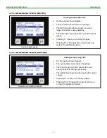
4.13. ANALOG OUTPUTS (AVG YDY) ..............................................................................................................16
4.14. ANALOG OUTPUTS (Max YDY) ...............................................................................................................16
4.15. ANALOG OUTPUTS (MinYDY) .................................................................................................................17
4.16. ANALOG OUTPUTS (AVG YDY) ..............................................................................................................17
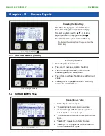
Chapter - 5.
Sensor Inputs
.......................................................................................................................
18
5.1.
SENSOR INPUTS (Value) .........................................................................................................................18
5.2.
SENSOR INPUTS (Type) ..........................................................................................................................18
5.3.
SENSOR INPUTS (Last On) .....................................................................................................................19
5.4.
SENSOR INPUTS (Last Off) .....................................................................................................................19
5.5.
SENSOR INPUTS (Max TDY) ...................................................................................................................19
5.6.
SENSOR INPUTS (Min TDY) ....................................................................................................................20
5.7.
SENSOR INPUTS (Run TDY) ...................................................................................................................20
5.8.
SENSOR INPUTS (Avg TDY) ....................................................................................................................20
5.9.
SENSOR INPUTS (Cycles TDY) ...............................................................................................................21
5.10. SENSOR INPUTS (RUN YDY) ..................................................................................................................21
5.11. SENSOR INPUTS (Max YDY) ...................................................................................................................21
5.12. SENSOR INPUTS (Cycles YDY) ...............................................................................................................22
5.13. SENSOR INPUTS (Min YDY) ....................................................................................................................22
5.14. SENSOR INPUTS (TTL Run HR) ..............................................................................................................22
5.15. SENSOR INPUTS (Avg YDY) ...................................................................................................................23


