background image

gizing a 220 volt heater.

This causes the normally

closed bi-metallic relay switch of this control to open
after a delay of approximately 90 seconds or less,

stopping the compressor and closing the liquid line
solenoid valve. The time delay prevents nuisance trip
out on momentary low suction pressure and permits the
operation of the system on a “pumpdown cycle”.

The control must be checked while the system is

operating. To check the control, install a volt meter
or 220 volt light across terminal T1 and T2 of the low

pressure freeze control. There should be a voltage
indication or the test light will glow indicating the
contacts are opened. Throw the pumpdown switch to

the manual position and check the pressure at which
the test light goes out or the volt meter goes to zero.

In actual operation, the compressor wi II shut down and

the safety light will go out. The control can be man-
ually reset in about 2 minutes.

Thermostat - The thermostots supplied on all pack-

aged chillers are factory calibrated for use in the re-
turn water line to the cooler inlet. The thermostat

bulb is installed in a well in the return water line in
order to be more stable under temperature changes due
to load conditions. The return water does not change

temperature as rapidly as the outlet because of the

“fly whee I effect” of the total water system. This re-
sults in stable control of the outlet water temperature.
Normally the thermostat requires no adjustment in the
field other than the dial setting for the required con-
trol point.The control is preset at the factory to main-
tain a 44F average leaving water temperature through-
out the loading and unloading sequence of the unit,

based on a full load cooling range of 10F. It should
be realized, however, that there will be a fluctuation

in the leaving,water temperature as the unit cycles,

unloads and loads.

On a two stage thermostat, the dial setting indi-

cates the average leaving water temperature that the
control will maintain.At a 44F setting, the high stage

should actuate at approximately 51F return water and

41F leaving based on 10F. cooling range. The low

stage will open at 46F return or 41 F leaving (5F TD

or 50% capacity). As the water warms up, the low

stage should cut in at approximately 49F which is the
inlet and outlet temperature with the unit off and the
high stage should operate at 54F return or 49F leaving.

These settings may be checked by operating the

unit and slowly regulating the load from full to mini-
mum and return. It may then be necessary to adjust the
dial and/or differential between switches to obtain
these values.

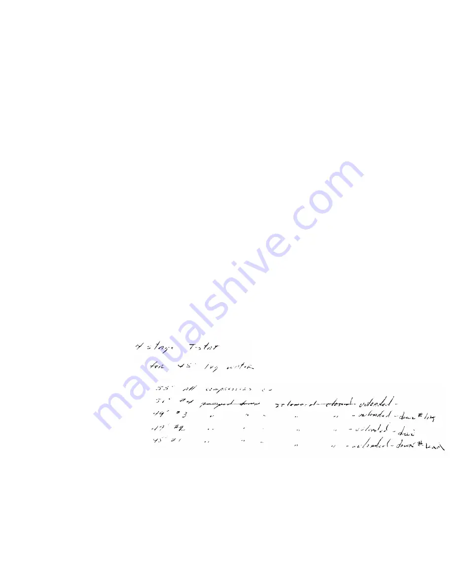
On a four stage thermostat, the dial setting indi-

cates the cut out point of the low stage switch which
represents the average leaving water temperature de-

sired. The high stage or #4 switch should be actuated

at approximately 51F return water temperature, #3 at
49F, #2 at 47F and #1 at 45F which is the dial setting.
The cut in point will be approximately 2F higher than
the cut out on each switch.

These settings may be checked by operating the

unit and slowly reducing the load. The four stage

thermostat has a fixed switch differential and fixed
differential between switches. DO NOT make any ad-

justments other than the dial as this is a preset pre-

cision control.

CAUTION: Response time on thermostat is slow, con-

sequently, approximately 5 minutes must be allowed

for bulb response (after attaining system steady-state
operotion) before any or each adjustment to thermo-

stat is made.

Page 25

Содержание Seasonpak PWA-008A

Страница 1: ...BLE OF CONTENTS CONTROLS CHECKING 24 CROSSREFERENCE NEW TO OLD MO 2 ELECTRICAL 22 23 CONTROL CENTER SERVICE 26 27 ELECTRICALDATA 22 23 WIRING 10 13 WIRING DIAGRAMS 14 21 MAINTENANCE 26 29 MOVING PLACI...

Страница 2: ...LL UNIT FROM ANYTHING OTHER THAN water cooled condensers Arrangement 1 is supplied THE BASE MOVING AND PLACING THE UNIT MOVING THE UNIT The McQUAY SEASONPAK water chiller is mounted on heavy wooden sk...

Страница 3: ...EARANCE FOR COOLER TUBE RE MOVAL MEASURED FROM CENTER LINE OF CHILLED WATER CONNECTION ON EITHER END TABLE NO 1 MINIMUM CLEARANCE UNIT SIZE I MINIMUM CLEARANCE 007A THRU 015A 72 020A THRU 041A 96 050A...

Страница 4: ......

Страница 5: ......

Страница 6: ...nded beyond the pro FIGURE NO 7 TO COOI ER 4 posed insulation thickness to make them accessible CHILLED WATER THERMOSTAT WHR 008A thru 060A The chilled water thermostat is mounted inside the control c...

Страница 7: ...oop at the outlet end is recommended See Figure 9 WATER REGULATING VALVES EACH CONDENSER FIGURE NO 8 3 WAY WATER REGULATING VALVES COi lNG TOWER PURGE 4 MAIN CONDENSER WATER SUPPLY FROM PUMP BY PASS B...

Страница 8: ...cal discharge riser is too low considerable oil may collect in the riser and the horizontal header causing the compressor to lose its oil and resultant damage due to lack of lubrication Another danger...

Страница 9: ...E NO 11 PURGE VALVE DISCHARGE LINE HECK VALVE LIQUID LINE FIGURE NO 13 DISCHARGE LINE I TO EVAPORATOR RECEIVER LrQuro LINE EVAPORATORS or and receiver The discharge line piping in this case is not too...

Страница 10: ...TAT 12 INDICATOR LIGHTS 6 HIGH MANUAL RESET AND LOW PRESSURE CUTOUTS 7 CONTROL SYSTEM ON OFF SWITCH FIGURE NO 16 MODELS WHR 070A THRU 120A 1 FREEZESTAT MANUAL RESET 7 CONTROL SYSTEM ON OFF SWITCH 2 OI...

Страница 11: ...020A THRU 060A FIGURE NO 17 TOP VIEW OF UNIT Models WHR OO8A thru 015A are single compressor units 3 4 5 6 7 8 9 10 25 The power from 25 is fed thru NC contacts to relay R3 and R4 to energizethe compr...

Страница 12: ...e operating before power can be applied to start this system Note that the crankcase heaters will be energized regard less of water flow The flow switch is recommended and does not have the shortcomin...

Страница 13: ...itch LP1 opens Contactors Ml M3 and relay R3 will open and compressor 1A will turn off and stay off until relay R1 is again energized thru the thermostat In the event compressor 1A is off on oil press...

Страница 14: ......

Страница 15: ......

Страница 16: ......

Страница 17: ......

Страница 18: ......

Страница 19: ......

Страница 20: ......

Страница 21: ......

Страница 22: ......

Страница 23: ......

Страница 24: ...aches the prescribed differential within 120 seconds the thermal time delay is de energized and the control circuit remains closed If during the operation the oil pressure differential falls below 10...

Страница 25: ...d unloading sequence of the unit based on a full load cooling range of 10F It should be realized however that there will be a fluctuation in the leaving water temperature as the unit cycles unloads an...

Страница 26: ...eaning of the finned surface of the conden ser coil Cleaning may be accomplished by using a cold water spray brushing vacuuming or high pres sure air No tools should be used that could damage the coil...

Страница 27: ......

Страница 28: ...s t e m c P u r g e t h e n o n c o n d e n s i b l e s d S y s t e m o v e r c h a r g e d w i t h r e f r i g e r a n t d R e m o v e e x c e s s e D i s c h a r g e s h u t o f f v a l v e p a r t...

Страница 29: ...n d t i g h t e n s y s t e m k R e p l a c e g a s k e t I Adjust t h e r m a l e x p a n s i o n v a l v e C o m p r e s s o r l o s e s o i l _ _ _ a L a c k o f r e f r i g e r a n t a C h e c k f...

Страница 30: ...ber and serial number of the date of installation of the unit and date of failure along with an explanation of the malfunctions and a the unit as stamped on the serial plate attached to the unit If re...

Отзывы: